Introduction
Different treatment modalities have been proposed for the management of distal extension cases, with the removable partial denture being the least acceptable by the patients. This is due to the nature of the prosthesis support which is derived from both the abutment teeth and the residual ridge. The mucosa covering the residual ridge shows a higher degree of compressibility which is twenty times more than that of the abutment tooth. This disparity of support subjects the abutment tooth to leverage action as reported by McGivney and Carr (2000).
The use of dental implants to provide support for the prosthesis offers many advantages when compared to removable tooth-tissue borne restorations. Implant-supported prostheses provide a more stable occlusal relationship, better retention and improved chewing efficiency, when compared to tooth-tissue borne prostheses as indicated by Geertman et al (1994).
Teixeira et al (1997) considered the use of short implants as a successful solution in areas lying in close proximity to the maxillary sinus or the inferior dental canal. Implants could be used to support a removable prosthesis using a combination of unilateral or bilateral single molar implants with ball attachments, thus changing the situation from a Kennedy Class I or II partially edentulous case into a Class III case allowing the patient to benefit from both the improved support, as well as retention.
Mahon et al (2000) found that the use of wide-diameter implants could be of value in providing more bone-to-implant contact in cases of poor bone quality, limited crestal bone height and immediate placement in failure sites. However, the use of wide implants may lead to possible over-instrumentation and heat generation. The use of implants less than 5 mm in diameter has been proposed by Ivanoff et al (1999) and English et al (2000) to reduce the heat generated in the drilling process and subsequent bone damage.
A study by Griffin and Cheung (2004) revealed that the use of implant-supported partial over-dentures could be considered an acceptable treatment modality for such cases where the support of the prosthesis is derived from both the abutment teeth and the implant. However, the placement of dental implants in the posterior region may be limited by its proximity to vital anatomical structures such as the maxillary sinus, inferior alveolar neuro-vascular bundle, as well as the presence of a reduced residual ridge height.
De Carvalho et al (2001) and Mijiritsky et al (2005) mentioned that a limited number of strategically placed dental implants in conjunction with the remaining natural teeth can establish a favorable removable partial over-denture design by significantly reducing the effect of the reciprocal arm and improving the fulcrum line position. Thus, additional retention is achieved and the need for an unaesthetic buccal retentive arm is avoided at the esthetic zone.
It was found by Misch (2005) that implant restoration allows for the use of reduced flanges and plates of the prosthesis, which are of special benefit for new denture wearers, who often complain of the increased bulk of the restoration. Moreover, the taste sensation is improved due to the decreased tissue coverage when compared to conventional dentures. Posteriorly placed major connectors in the maxillary denture may annoy the tongue and cause gagging sensation in some patients which could be eliminated totally by the use of an implant-supported partial over-denture. Misch also added that the softer the bone, the greater the length suggested, where the increase in the length of an implant leads to an increase in the total surface area of that implant. As a result, a common axiom was to place an implant as long as possible and, preferably, into the opposing cortical plate. However, this axiom is only applicable in the anterior mandible, where the bite forces are already less and the bone density is great compared to other regions of the jaws.
Moreover, Grant et al (2009) proposed various strategies to overcome the anatomic and physiologic limitations of implant placement. Surgical interventions like guided bone regeneration, distraction osteogenesis, and nerve transposition were suggested. However, some patients reject undergoing multiple surgeries. Besides, additional treatment duration and financial burden could discourage patients’ motivation. The use of a short wide implant in the areas with decreased bone height to minimize the need for additional surgeries for acceptable implant placement has also been suggested.
There are many techniques of stress analysis used in dental research; the most commonly used ones are the mechanical dial gauges recommended by Nally (1973), stereophotogramatic analysis recommended by Eick et al (1987), photoelastic studies recommended by Eisenmann and Walter (2004), strain gauge technique recommended by Asundi and Kishen (2000) and Pitt et al (2006) and the Finite Element Method (FEM).
The Finite Element Method is a numerical procedure used for analyzing structures and it allows investigators to assess stresses and strains within a solid body as indicated by Wadamoto et al (1996). Most Finite Element Models assume a state of optimal osseointegration, meaning that cortical and trabecular bones are assumed to be perfectly bonded to the implant, although this does not exactly occur in clinical situations. Lai et al (1998) found that the most extreme stresses in the bone were always located around the neck of the implant. Those stresses in the implant-tissue interface decreased in inverse proportion to the increase in percentage of osseointegration.
A controversy exists about whether increasing the implant length or diameter is more effective on the stress distribution to the supporting structures in implant-supported partial over-dentures.
Therefore, this study was conducted to evaluate the effect of changing implant dimensions on the stress distribution in the supporting structures in implant-supported partial over-dentures.
Materials and Methods
A partially edentulous male patient was selected with an age of forty five years. The patient had lost all the molars on one side of the lower arch (Kennedy Class II) with a good condition of the abutment teeth as detected clinically and radiographically with normal ridge relationship (Angle Class I maxillomandibular relationship). The alveolar ridge was moderate in size and covered by firm mucoperiosteum. The subject was free from any systemic disease that could affect the prosthodontic treatment.
A skeleton partial over-denture was fabricated in the conventional technique. A physical model was then constructed where the CT image acquisition was performed in a DICOM (Digital Imaging Communications in Medicine) format using Asteion 4 multi-slice CT scanner*. Entering the data was followed by a segmentation procedure. First, a mask was constructed containing all the elements in the study. This was done by taking the minimal density of the most translucent element and the maximum density of the most radio-opaque element. This mask was named full density mask. Then, by cropping, a three dimensional (3D) model was constructed from that mask by selecting a new 3D object and then calculation was done. Thus, the resulting 3D model contained all the regions of the study.
Then, the mask representing the most radio-opaque material in the structure which was the metal framework was constructed. The metal had a radio-density of 3071 Housefield Units (HU) which is the maximum available on the threshold gauge. After separation of the metal mask, this mask was subtracted from the original mask (full density) using Boolean operation which is a special option available in the system to have a mask containing all elements except the metal. The teeth mask was separated having a density ranging from 1750-2500 HU. The resultant mask was further subtracted from the second mask (full density minus metal) and so on until all the elements were separated into separate masks. Acrylic resin of the denture was also separated into a separate mask. Then, meshing of the 3D objects was performed using Magics software*. First, smoothening of the object was carried out, and then auto-remeshing was performed.
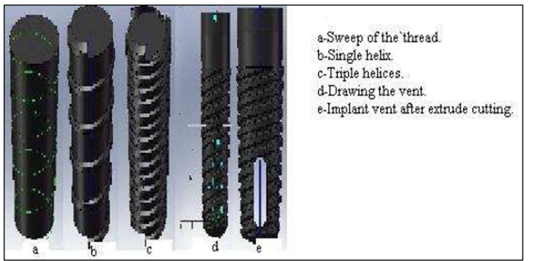
The implant body was drawn using solid works software**. It was constructed by drawing half of the outline of the implant on a two dimensional sketch and then using the option of 360 degrees revolving to construct a 3D model. The threads were constructed by drawing the cross section of the thread at its point of origin and then, using the 3D sweep option to draw its helical path over the implant body. Triple helices were drawn independently one by one. The vent of the implant was drawn using the extrude cut option near the apex of the implant (Fig. 1). The implant lengths*** used were 10, 11.5 and 13mm and the implant diameters were 3.75, 4.7 and 5.7mm.
Figure1: Drawing of the implant.
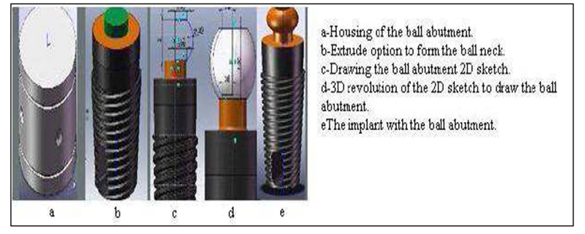
The ball and socket attachment was constructed by drawing half of the outline of the ball abutment on a two dimensional sketch and then, using the option of 360º revolving to construct a 3D model of the ball abutment (Fig.2). Construction of the Finite Element Model was achieved through two stages, pre-processing and post-processing. A 100 Newton (N) masticatory load in vertical and oblique directions (45 degrees) was applied to the prosthesis. The vertical load was directed to the central fossae (Fig.3), while the oblique load was applied to the lingual inclines of the buccal cusps in the molar region. All the stress values obtained for different implant lengths and diameters were imported to an Excel 2010 (technical preview sheet), where a comparison between the stresses induced in the different model elements was done using the percentage difference index according to the following:
Von Mises Stresses
It was found that, even though none of the principal stresses exceeds the yield stress of the material, it is possible for yielding to result from the combination of stresses. The Von Mises stresses indicate the resultant stresses in Mega Pascal (MPa) at each specified element in the specified volume. Thus, the Von Mises criterion is a formula for combining the following stresses into an equivalent stress:
(S1-Sint.)2 + (Sint.-S3)2 + (S3-S1)2 = 2Se2
Where: Se is the equivalent Von Mises stresses
S1 is the principle tensile stress
S3 is the maximum compressive stress
S integrated (int.) is the principle shear stress
Figure2: Drawing of the ball abutment and housing.
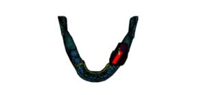
Figure 3: Vertical load of 100N applied to the molar area
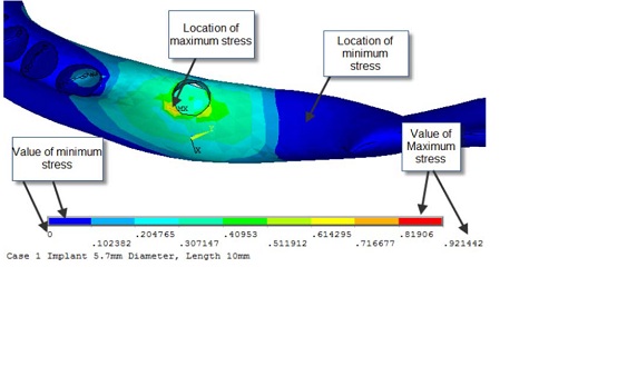
Results were obtained for each element examined in the study, i.e. compact bone, cancellous bone, implant, metal framework, denture base and the teeth (Fig. 4). Then, all the stress values obtained for the different implant lengths and diameters were imported to an Excel 2010 (technical preview sheet), where a comparison between the stresses induced in the different model elements was done using the percentage difference index according to the following equations:
Percentage Change in stresses with the increase in length) =L2 – L1) /L1 X100
– L2 is the stress obtained using length 2 of the implant and L1 is the original implant length.
– The same was done for the difference between L1 and L3 and L2 and L3
Percentage Change in stresses with the increase in diameter) =D2 – D1) /D1 X100
– D2 is the stress obtained using diameter 2 of the implant and D1 is the original implant diameter.
– The same was done for the difference between D1 and D3 and D2 and D3.
The data obtained from the above mentioned equations indicated the percentage increase or decrease in the stresses induced in the different model elements by utilizing different lengths and diameters of the dental implant.
Figure 4: Location of minimum and maximum stresses
This study was concerned with the evaluation of three different implant lengths and diameters (more than two variables). Therefore, comparisons between the resultant changes in stresses were statistically evaluated using the RM ANOVA test (Repeated Measures Analysis of Variances). The RM ANOVA was done using the SIGMAPLOT 11 (SYSTAT INC)*.
Results
Von Mises Stresses
Under unilateral vertical loading
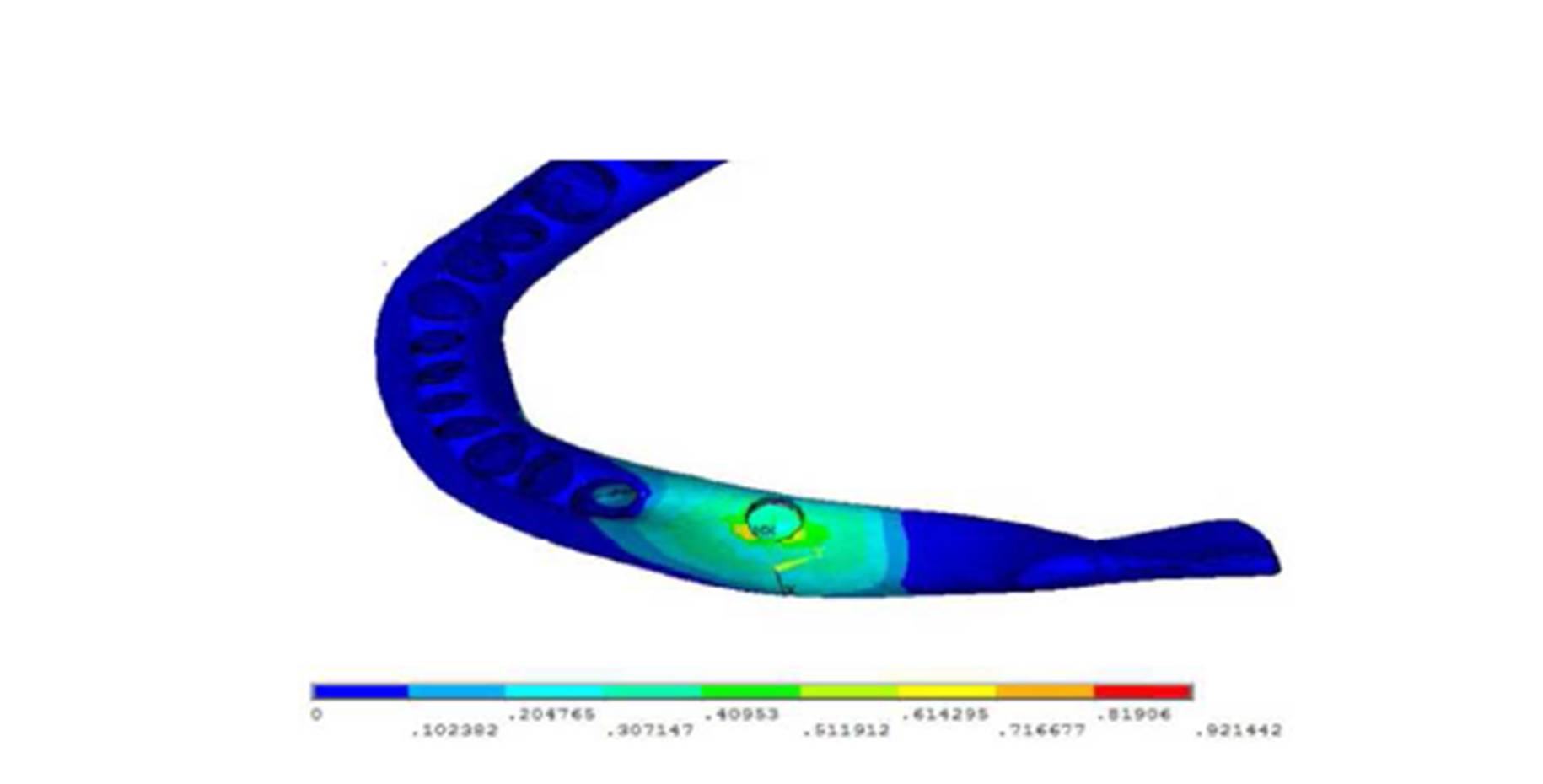
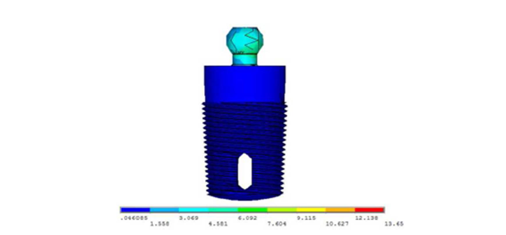
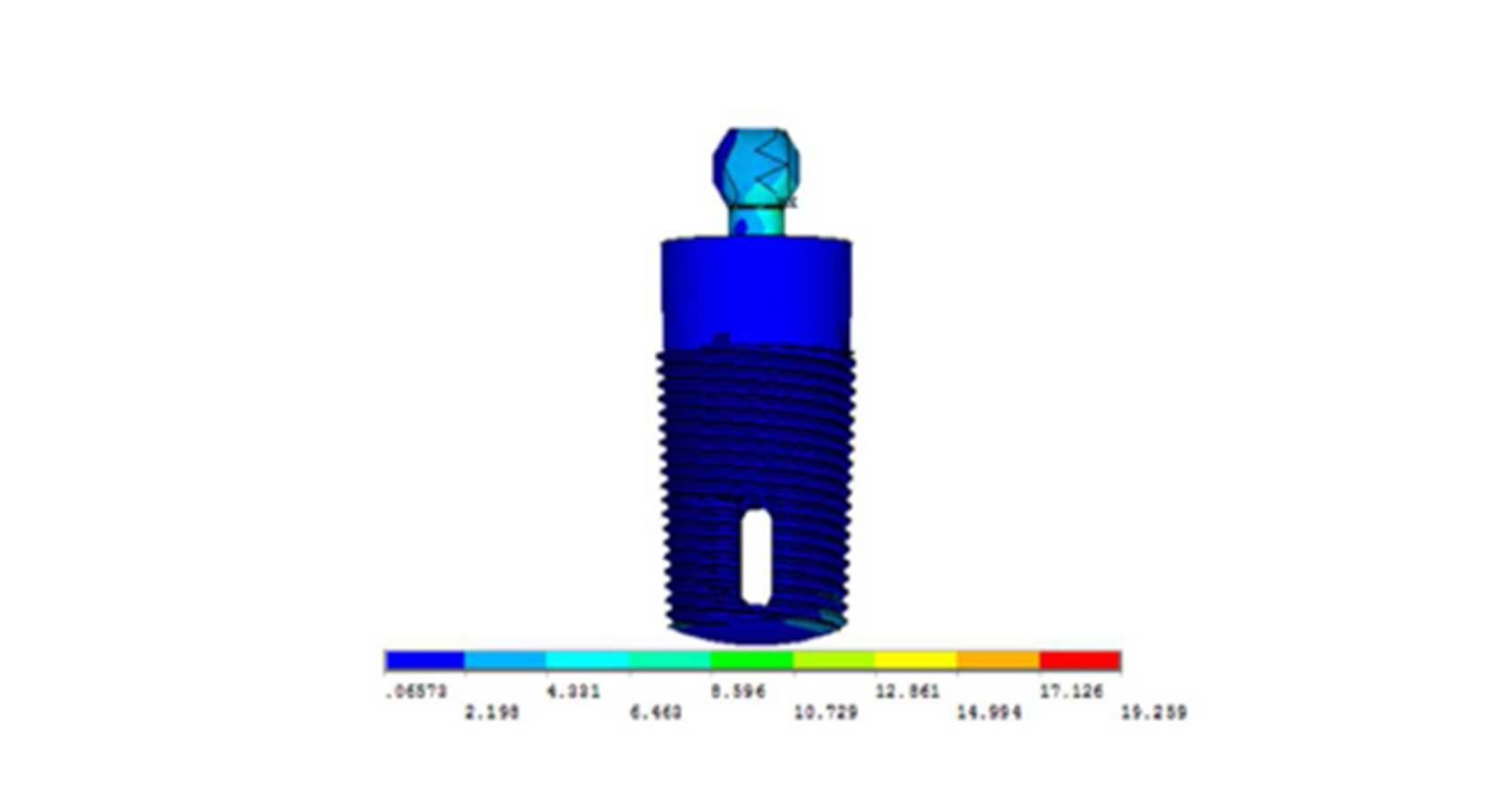
Analysis of the vertical loading demonstrated an uneven stress distribution in the supporting structures around the loaded implant. The maximum stresses in the bone were present around the implant neck on the buccal side (the area indicated by the red color), while the lowest stresses were present at the apical part of the bone cylinder on the lingual side (cancellous bone) (Fig.5). Regarding the implant, most of the stresses were present around the ball abutment, while the minimal stresses were present around the implant body (Fig.6). However, for the abutment tooth, the highest stresses were observed at the distal aspect of the root apex. In the denture base and the metal framework, the maximum stresses were found in the area around the implant. These locations of highest and lowest stresses were identical with all the implant diameters and lengths used.

Figure 5: Von Mises stresses in the bone under unilateral vertical loading
Figure 6: Von Mises stresses in the implant under unilateral vertical loading
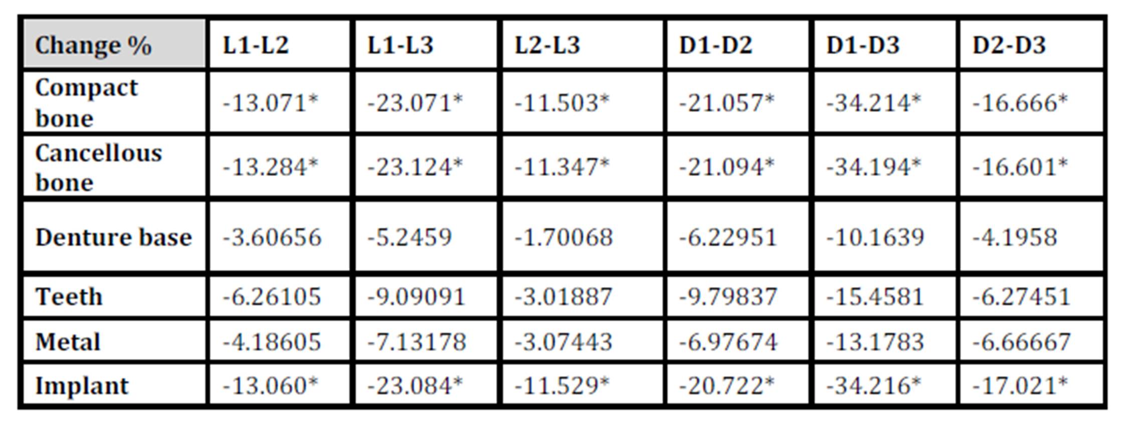
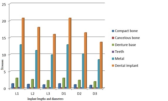
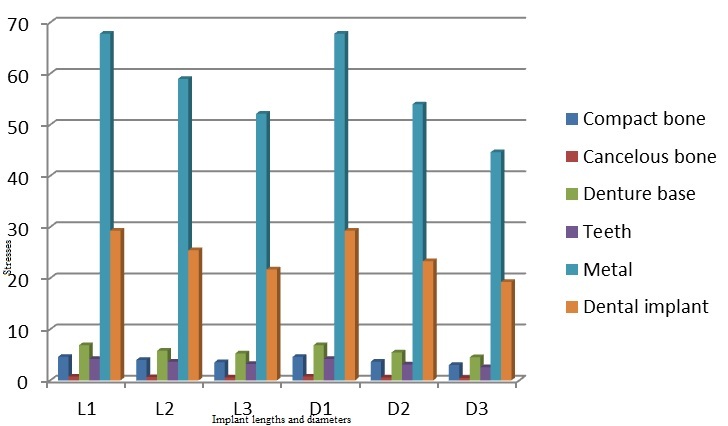
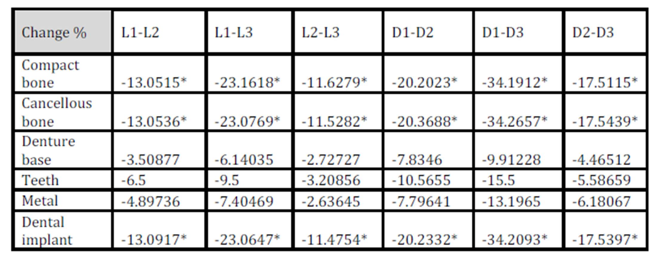
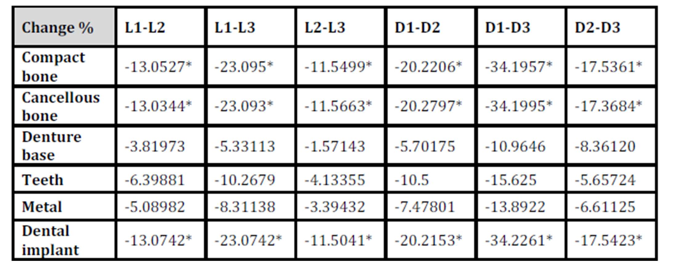
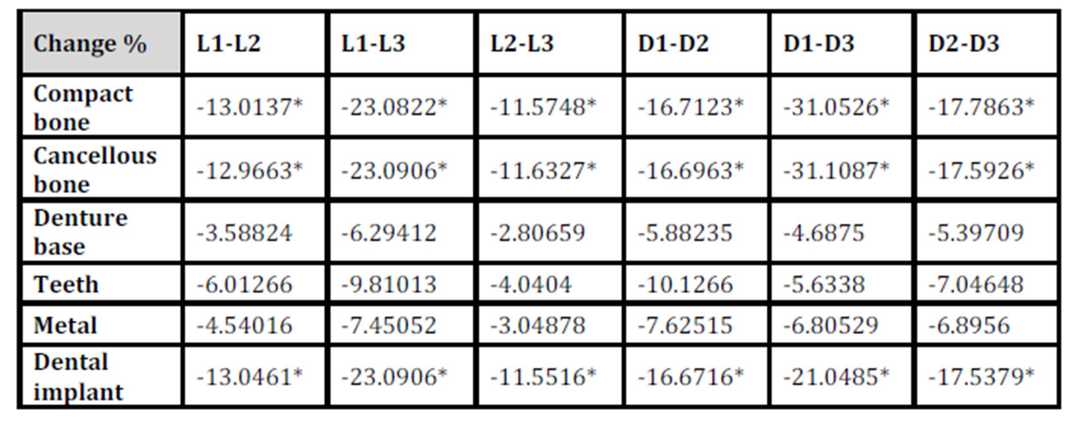
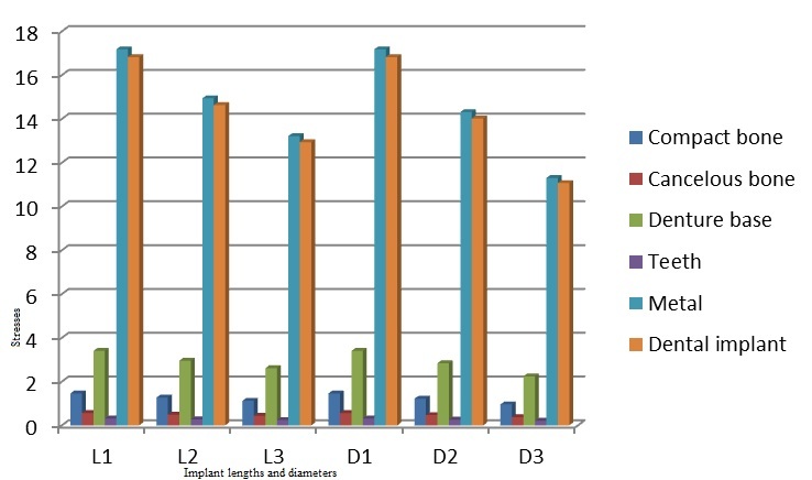
With the increase in the implant diameter, a statistically significant decrease (P≤0.05) in the Von Mises stresses was observed in the compact bone, cancellous bone and implant, as compared to the increase in the implant length. However, this decrease was statistically insignificant (P>0.05) in the denture base, metal framework and teeth. The percentage decrease in the stresses with the increase in the implant diameter ranged between 4.2% in the denture base to 34.2% in the compact bone, while the percentage decrease in the stresses with the increase in the implant length ranged between 1.7% in the denture base to 23.1% in the cancellous bone. (Table 1, Fig. 7)
Table 1: Percentage change in von Mises stresses under unilateral vertical loading
* P ≤ 0.05 is considered significant.
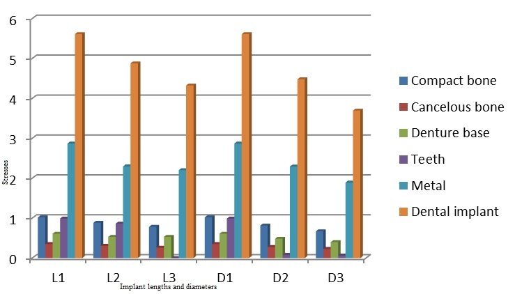
Figure 7: Von Mises stresses under unilateral vertical loading
Under unilateral oblique loading
Analysis of the oblique loading demonstrated that the maximum stresses in the compact bone were present around the implant neck on the buccal side. The maximum stresses in the cancellous bone were present on the buccal side of the apical part of the bone cylinder (Fig.8). Regarding the implant, most of the stresses were present around the ball abutment, while the minimal stresses were present around the implant body (Fig.9). However, for the abutment tooth, the highest stresses were observed at the area of the rest seat. In the denture base, the maximum stresses were found on the fitting surface of the denture near the abutment tooth. In the metal framework, the maximum stresses were found in the area of the occlusal rest.
Figure 8: Von Mises stresses in the bone under unilateral oblique loading
Figure 9: Von Mises stresses in the implant under unilateral oblique loading
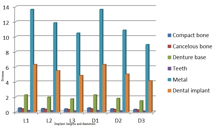
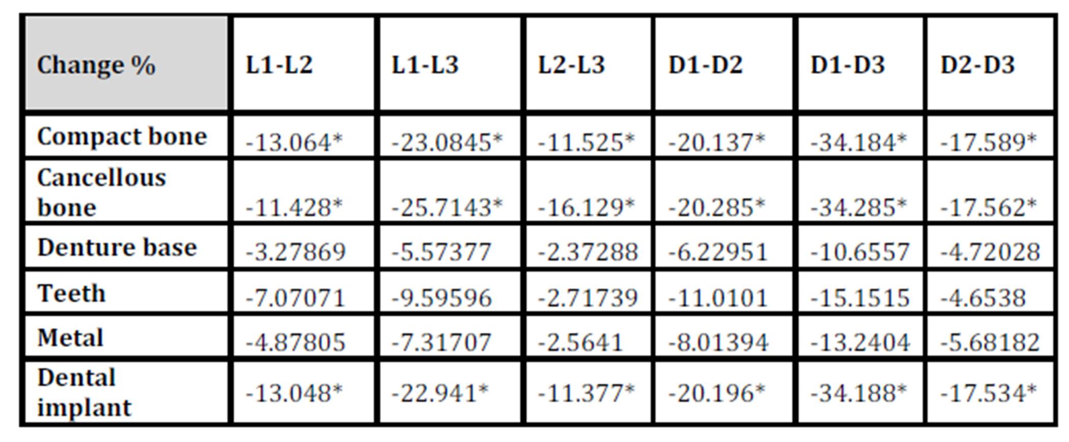
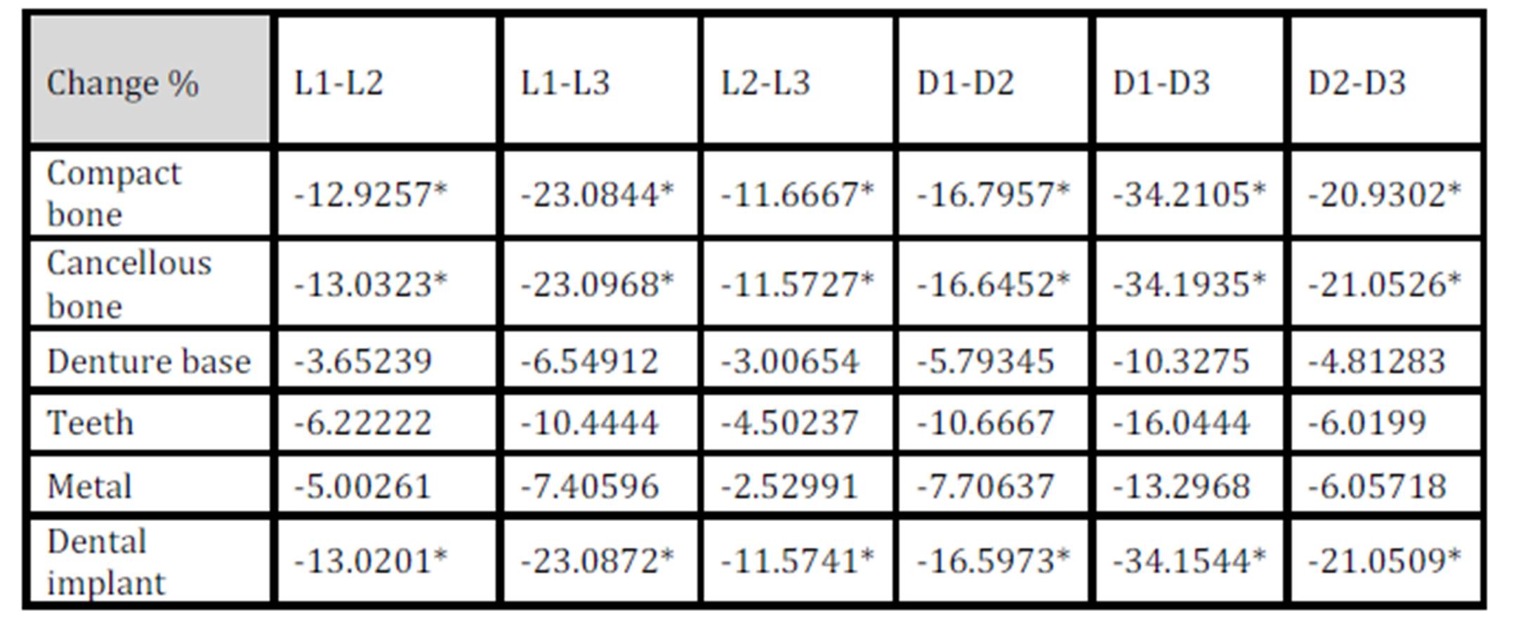
With the increase in the implant diameter, a statistically significant decrease (P≤0.05) in the Von Mises stresses was observed in the compact bone, cancellous bone and implant, as compared to the increase in the implant length. However, this decrease was statistically insignificant (P>0.05) in the denture base, metal framework and teeth. The percentage decrease in the stresses with the increase in the implant diameter ranged between 5.1% in the teeth to 35% in the cancellous bone, while the percentage decrease in the stresses with the increase in the implant length ranged between 2.3% in the teeth to 23% in the cancellous bone. (Table 2, Fig.10)
Table 2: Percentage change in von Mises stresses under unilateral oblique loading
* P ≤ 0.05 is considered significant.
Figure 10: Von Mises stresses under unilateral oblique loading
S1 stresses (principle tensile stress)
Under unilateral vertical loading
The maximum tensile stresses in the bone were present around the implant neck on the lingual side of the implant, while the minimal stresses were present at the apical part of the bone cylinder on the buccal side (cancellous bone). Regarding the implant, most of the stresses were present around the neck of the ball abutment. However, for the abutment tooth, the highest stresses were observed at the area of the occlusal rest seat. The maximum stresses in the denture base were found around the metal framework towards the abutment tooth, while the maximum stresses in the metal framework were found in the area around the implant.
With the increase in the implant diameter, a statistically significant decrease (P≤0.05) in the maximum tensile stresses was observed in the compact bone, cancellous bone and implant, as compared to the increase in the implant length. However, this decrease was statistically insignificant (P>0.05) in the denture base, metal framework and teeth. The percentage decrease in the stresses with the increase in the implant diameter ranged between 4.4% in the denture base to 34.2% in the cancellous bone, while the percentage decrease in the stresses with the increase in the implant length ranged between 2.7% in the denture base to 23.1% in the compact bone. (Table 3, Fig.11)
Table 3: Percentage change in S1 stresses under unilateral vertical loading
* P ≤ 0.05 is considered significant.
Figure 11: S1 stresses under unilateral vertical loading
Under unilateral oblique loading
The maximum tensile stresses in the bone were present around the lingual side. Most of the stresses in the implant were seen around the neck of the ball abutment. Regarding the abutment tooth, the highest stresses were observed at the area of the occlusal rest seat. The maximum stresses in the denture base were present on the mesial aspect, while in the metal framework, they were found in the area of the occlusal rest.
With the increase in the implant diameter, a statistically significant decrease (P≤0.05) in the maximum tensile stresses was observed in the compact bone, cancellous bone and implant, as compared to the increase in the implant length. However, this decrease was statistically insignificant (P>0.05) in the denture base, metal framework and teeth. The percentage decrease in the stresses with the increase in the implant diameter ranged between 5.6% in teeth to 43.2% in the cancellous bone, while the percentage decrease in the stresses with the increase in the implant length ranged between 1.5% in the denture base to 23.1% in the compact bone (Table 4, Fig.12)
Table 4: Percentage change in S1 stresses under unilateral oblique loading
* P ≤ 0.05 is considered significant.
Figure12: S1 stresses under unilateral oblique loading
S3 (maximum compressive stress)
Under unilateral vertical loading
The maximum compressive stresses in the bone were present around the neck of the implant and the neck of the abutment tooth. Regarding the implant, the maximum stresses were found around the neck of the ball abutment. However, for the abutment tooth, the highest stresses were observed at the area of the occlusal rest seat. In the denture base, the maximum stresses were found at the borders of the buccal and lingual flanges and in the area adjacent to the abutment tooth, while in the metal framework, the maximum stresses were found in the area around the dental implant.
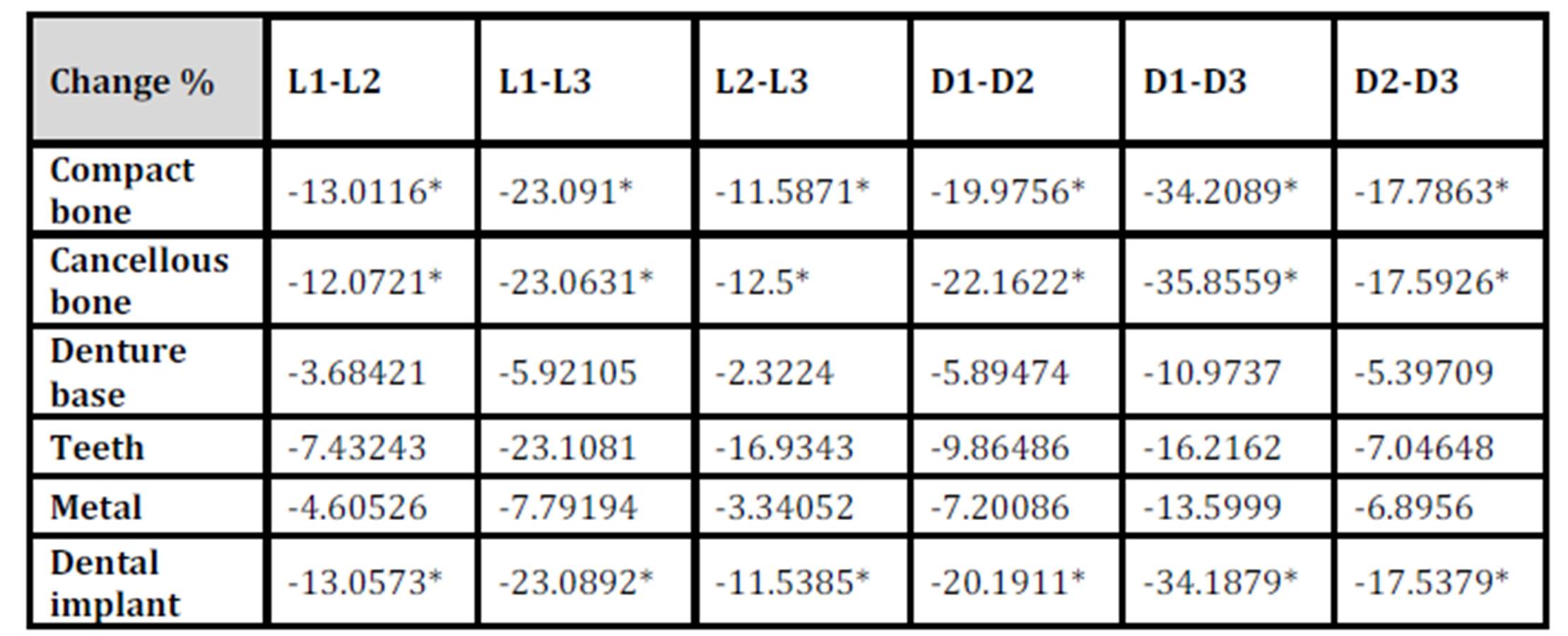
With the increase in the implant diameter, a statistically significant decrease (P≤0.05) in the maximum compressive stresses was observed in the compact bone, cancellous bone and implant, as compared to the increase in the implant length. However, this decrease was statistically insignificant (P>0.05) in the denture base, metal framework and teeth. The percentage decrease in the stresses with the increase in the implant diameter ranged between 4.6% in the teeth to 34.2% in the cancellous bone, while the percentage decrease in the stresses with the increase in the implant length ranged between 2.3% in the denture base to 25.7% in the compact bone. (Table 5, Fig.13)
Table 5: Percentage change in S3 stresses under unilateral vertical loading
* P ≤ 0.05 is considered significant.
Figure 13: S3 stresses under unilateral vertical loading
Under unilateral oblique loading
The maximum compressive stresses in the bone were present around the neck of the implant and the neck of the abutment tooth. Regarding the implant, the maximum stresses were found around the neck of the ball abutment. However, for the abutment tooth, the highest stresses were observed at the area of the occlusal rest seat and on the mesial surface adjacent to the minor connector. In the denture base, the highest stresses were found at the lingual flanges and in the area adjacent to the abutment tooth, while in the metal framework, the maximum stresses were found in the area of the rest seat.
With the increase in the implant diameter, a statistically significant decrease (P≤0.05) in the maximum compressive stresses was observed in the compact bone, cancellous bone and implant, as compared to the increase in the implant length. However, this decrease was statistically insignificant (P>0.05) in the denture base, metal framework and teeth. The percentage decrease in the stresses with the increase in the implant diameter ranged between 5.3% in the denture base to 35.8% in the cancellous bone, while the percentage decrease in the stresses with the increase in the implant length ranged between 2.3% in the denture base to 23.1% in the compact bone. (Table 6, Fig.14)
Table 6: Percentage change in S3 stresses under unilateral oblique loading
* P ≤ 0.05 is considered significant.
Figure 14: S3 stresses under unilateral oblique loading
S int. (principle shear stress)
Under unilateral vertical loading
The maximum shear stresses in the bone were present on the side at the implant neck and around the vent of the implant. The maximum shear stresses in the implant were present in the neck of the ball abutment. However, for the abutment tooth, the highest stresses were found at its distal aspect. In the denture base, the maximum stresses were found at the buccal side adjacent to the ball abutment, while in the metal framework, the maximum stresses were found in the area around the dental implant.
With the increase in the implant diameter, a statistically significant decrease (P≤0.05) in the maximum shear stresses was observed in the compact bone, cancellous bone and implant, as compared to the increase in the implant length. However, this decrease was statistically insignificant (P>0.05) in the denture base, metal framework and teeth. The percentage decrease in the stresses with the increase in the implant diameter ranged between 4.6% in the denture base to 31.1% in the cancellous bone, while the percentage decrease in the stresses with the increase in the implant length ranged between 2.8% in the denture base to 23.1% in the compact bone. (Table 7 Fig.15)
Table 7: Percentage change in S int. stresses under unilateral vertical loading
* P ≤ 0.05 is considered significant.
Figure 15: S int. stresses under unilateral vertical loading
Under unilateral oblique loading
The maximum shear stresses in the bone were present on the buccal side of the implant neck and at the apical part of the dental implant. The maximum shear stresses in the implant were present in the neck of the ball abutment. However, for the abutment tooth, the highest stresses were found at the area of the occlusal rest seat. In the denture base, the maximum stresses were found at the mesial part of the fitting surface, while in the metal framework, the maximum stresses were found in the area of the occlusal rest.
With the increase in the implant diameter, a statistically significant decrease (P≤0.05) in the maximum shear stresses was observed in the compact bone, cancellous bone and implant, as compared to the increase in the implant length. However, this decrease was statistically insignificant (P>0.05) in the denture base, metal framework and teeth. The percentage decrease in the stresses with the increase in the implant diameter ranged between 4.8% in the denture base to 34.2% in the compact bone, while the percentage decrease in the stresses with the increase in the implant length ranged between 3% in the denture base to 23.1% in the compact bone. (Table 8, Fig.16)
Table 8: Percentage change in S int. stresses under unilateral oblique loading
* P ≤ 0.05 is considered significant.
Figure 16: S int. stresses under unilateral oblique loading
Discussion
In this study, a Kennedy Class II partially edentulous case was selected and the construction of a skeleton partial denture was carried out. Then, a CT scan was carried out for the patient to create a three-dimensional model for the finite element analysis. This offered many advantages, including the possibility of accurate three-dimensional visualization and quantification of the internal structure of materials using a series of two-dimensional cross-sectional CT images. However, there are some limitations for this study as the presented model was only an approximation of the clinical situation. Therefore, the basic purpose of finite element studies is to explore the findings relevant to the risk factors instead of experiencing them in clinical applications. Another limitation of this study, as in all finite element studies, is that it assumes that there is a 100% bone to implant contact along the whole surface of the implant. Such an assumption is not true as the maximum bone to implant contact for the densest bone with a threaded implant does not exceed 80% as reported by Misch (2005).
The stresses around dental implants are affected by many factors. The present study was concerned mainly with the effect of the implant length and diameter. The stress distribution in the bone around the implant depends upon the shape and size of the implant. The results of this simulation study have shown that the implant diameter was more important for improving the stress distribution than the implant length. This may be attributed to the fact that the stress distribution inside the bony socket is uneven as the elements exposed to the maximum stresses are located around the neck. The stresses induced by the occlusal loads might immediately be transferred from the implant to the cervical cortical bone, whereas much lower remaining stresses may spread to the cancellous bone at the apical region. It is well known that the higher stress-transferring ability of the cortical bone is due to its higher modulus of elasticity compared with the cancellous bone. This is in accordance with the findings of Lai et al. (1998) and Himmlová et al (2004). Therefore, the wider area in the cervical portion of the implant may better dissipate the masticatory forces.
It was also clear from the results of the present study that increasing the implant diameter and length was accompanied by a corresponding reduction in the amount of the induced stresses. However, the higher stresses around the implant neck may be attributed to the fact that this area is mainly subjected to non-axial masticatory forces, which act in a lingual (oblique) direction as in grinding movements, in comparison to the chopping movements, which act in an axial direction. This situation corresponds to the findings of non-parametric computerized models of loaded dental implants by Meijer et al (1996) and Lai et al (1998).
The higher stress values of the oblique loading compared to the vertical loading could be attributed to the fact that the non-axial forces tend to cause uneven stress distribution leading to areas of higher stresses and others of low stresses. This coincides with the findings of Barbier et al (1998).
It is worth to mention that the effect of increasing the implant diameter and length on the stresses transferred to the supporting structures was more pronounced in the dental implant, cancellous bone and compact bone than its effect on the teeth, denture base or metal framework. This may be related to the biomechanics of tooth-implant-supported partial over-dentures as the forces are transmitted first to the denture base and then to the metal framework, the teeth and finally to the dental implants. Then, the dental implants transmit the forces to the compact bone, the cancellous bone and the least amount to the abutment teeth.
Conclusions
From the results of this study, it could be achieved that:
1) the increase in the implant diameter significantly reduced the stresses transmitted to the supporting bone compared to increasing the implant length.
2) the wider the implant diameter, the better the dissipation of the masticatory forces.
References
1) Asundi, A. and Kishen, A. (2000) “A strain gauge and photoelastic analysis of in-vitro strain and in-vitro stress distribution in human dental supporting structures,” Archives of Oral Biology, 45: 543-550.
Publisher – Google Scholar
2) Barbier, L., Vander Sloten, J., Krzesinski, G., Schepers, E., and Van der Perre, G. (1998) “Finite element analysis of non-axial versus axial loading of oral implants in the mandible of the dog,” Journal of Oral Rehabilitation, 25, 847-858.
Publisher – Google Scholar
3) De Carvalho, W.R., Baboza, E.P. and Caula, A.L. (2001) “Implant-retained removable prosthesis with ball attachments in partially edentulous maxilla,” Implant Dentistry, 10: 280-284.
Google Scholar
4) Eick, J.D., Browning, J.D., Stewart, C.D. and McGarrah, H.E.(1987) “Abutment tooth movement related to fit of a removable partial denture,” Journal of Prosthetic Dentistry, 57: 66-72.
Publisher – Google Scholar
5) Eisenmann, E. and Walter, M. (2004) “Improving the fit of implant supported superstructures using the spark erosion technique,” International Journal of Oral and Maxillofacial Implants, 19: 810-818.
6) English, C., Bahat, O., Langer, B. and Sheets, C.G. (2000) “What are the clinical limitations of wide-diameter (4 mm or greater) root form endosseous implants?,” International Journal of Oral and Maxillofacial Implants, 15: 293-296.
7) Geertman, M. E., Slagter, A. P., van Waas, M. A. and Kalk, W. (1994) “Comminution of food with mandibular implant-retained overdentures,” Journal of Dental Research, 73: 1858-1864.
Google Scholar
8) Grant, B.T., Pancko, F.X. and Kraut, R.A. (2009) “Outcomes of placing short dental implants in the posterior mandible: A retrospective study of 124 cases,” Journal of Oral and Maxillofacial Surgery, 67(4)713-717.
Publisher – Google Scholar
9) Griffin, T.J. and Cheung, W.S. (2004) “The use of short, wide implants in posterior areas with reduced bone height: A retrospective investigation,” Journal of Prosthetic Dentistry, 92: 139-144.
Publisher – Google Scholar
10) Himmlová, L., Dostálová, T., Kácovský, A. and Konvičková, S. (2004) “Influence of implant length and diameter on stress distribution : A finite element analysis,” Journal of Prosthetic Dentistry, 91: 20-25.
Publisher – Google Scholar
11) Ivanoff, C.J., Grondahl, K., Sennerby, L., Bergtrom, C. and Lekholm, U. (1999) “Influence of variations in implant diameters: a 3- to 5-year retrospective clinical report,” International Journal of Oral and Maxillofacial Implants, 14: 175-182.
12) Lai, H., Zhang, F., Zhang, B., Yang, C. and Xue, M. (1998) “Influence of percentage of osseointegration on stress distribution around dental implants,” Chinese Journal of Dental Research,1:7-11.
Google Scholar
13) Mahon, J.M., Norling, B.K. and Phoenix, R.D. (2000) “Effect of varying fixture width on stress and strain distribution associated with an implant stack system,” Implant Dentistry, 9: 310-320.
Publisher – Google Scholar
14) McGivney, G.P. and Carr, A.B. (2000) Removable partial prosthodontics. Mosby Co., St. Louis,:10th ed. PP.25-32, 338-344, 73-189, 121.
15) Meijer, H.J., Starmans, F.J., Steen, W.H. and Bosman, F. (1996) “Loading conditions of endosseous implants in an edentulous human mandible: A three-dimensional finite-element study,” Journal of Oral Rehabilitation, 23:757-763.
Publisher – Google Scholar
16) Mijiritsky, E., Ormianer, Z. and Klinger, A. (2005) “Use of dental implants to improve unfavourable removable partial denture design,” Compendium of Continuing Education in Dentistry, 26:744-746.
Google Scholar
17) Misch, C.E. (2005) Dental Implant Prosthetics. 1st edition, St. Louis: Elsevier, USA.
18) Nally, J.N. (1973) “Methods of handling abutment teeth in class I partial dentures,” Journal of Prosthetic Dentistry, 30: 561-566.
Google Scholar
19) Pitt, V., Daintith, J. and Isaca, A. (2006) “Science encyclopedia, Hamylon, London, 1sted. PP. 81, 1973. Cited from Rady, AA : Stress analysis induced by distal extension prosthesis with extended extra-coronal attachments,” MSC thesis, Cairo University.
20) Teixeira, E.R., Wadamoto, M., Akagawa, Y. and Kimoto, T. (1997) “Clinical application of short hydroxylapatite-coated dental implants to the posterior mandible: A 5-year survival study,” Journal of Prosthetic Dentistry, 78: 166-171.
Publisher – Google Scholar
21) Wadamoto, M., Akagawa, Y., Sato, Y. and Kubo, T. (1996) “The three-dimensional bone interface of an osseointegrated implant. I: a morphometric evaluation in initial healing,” Journal of Prosthetic Dentistry, 76:170-175.
Publisher – Google Scholar