Introduction
The aim of this project is to reduce build-up-area in production hall CARGO LOADER and create space for new projects in the CL production hall. It is necessary to create a new layout in CL hall. Discrete event simulation will be used to verify the new variant of the layout.
Case Study of the Company
BOS Automotive products Ltd. deals with production and distribution of interior accessories for automobiles, such as storage systems, in particular bags and ski bags, sun visors for the windows, blinds covering the luggage compartment, safety and protective nets and various other accessories and luggage room.
Original State of CL Hall
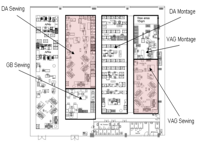
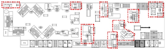
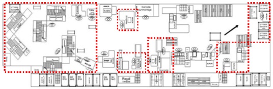
Figure 1 shows the layout of the CL hall with original arrangements, where all the workplaces are shown. One of the possibilities is to create new space by proposing a merger of sewing lines DA and VAG, because the machines on these lines are similar and the differences in some cases are only negligible parameters. Other differences are in mounting devices or worktables. One option for making a new place is to move some equipment from line VAG to line DA (The selection of machines will be carried out by comparing their parameters and shutdowns). In Figure 1, sewing lines are marked in red.
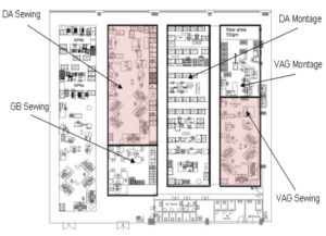
Fig 1. The CL Production Hall (Original State)
Material Flow of Sewing Line VAG
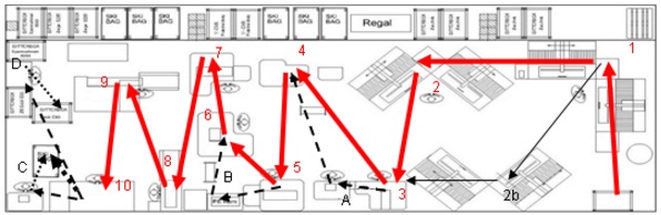
In Figure 2, you can see the sewing part of the VAG line. Flow of material is marked by arrows and individual workplaces are marked by numbers. Workplace 2b may be involved in the process because of lack of capacity in the workplace 2 machines (bend sewing). The thin arrow shows the flow divided to workplace 2 and workplace 2b. The dotted arrow represents the removal of the sewn bag from the sewing operations to the assembly operation.
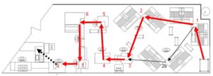 Fig 2. Material Flow – Sewing Line VAG
Cut leather comes to the first operation from KLT box as you can see in figure 1. In the first operation (belt sewing) belts are sewed onto the leather. The second operation is very similar; bands are sewed onto the leather (bands are harder belts). The next operation is gluing with white tape (this tape is glued under sewed bands and belts to waterproof the ski bag). Operation 5 is double-needle sewing. In this part of production process, leather is (with bands and belts) sewed to the bag. The next operation is gluing with black tape. The stitching around the whole bag is glued with black tape, and this operation is again to waterproof the bag. Operation 6 is turning the bag inside out and the last sewing operation is sewing polyethylene belt on the border of the bag.
Material Flow of Sewing Line DA
In Figure 3, as for the VAG line, material flow is marked by arrows, individual workplaces by numbers and the sewn bag leaving for mounting operations by the dotted arrow. Dashed arrows show the material flow for sewing bottom end – A, pressing belts – B and sewing additional plastic band – C. These operations are carried out on some exceptional products, and that is why these operations are not as important as the operations which are marked by numbers. Letter D is the workplace for pre-assembly of the frame for product E93. The thin arrow shows the flow which is divided into workplace 2 and workplace 2b as the VAG line.
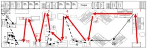
Fig 3. Material Flow – Sewing Line DA
Same as VAG line, cut leather comes to the first operation from KLT box as you can see in figure 1. In the first operation (belt sewing) belts are sewed onto the leather. The second operation is very similar, bands are sewed onto the leather (bands are harder belts). The next operation is zip sewing. From this workplace, some products go to workplace A (sewing additional bands). Operation 4 is again different from VAG line. The bottom is sewed at this workplace. The next operation is gluing with white tape. Operation 6 is a double-needle sewing. The next operation is gluing with black tape. Operation 8 is turning the bag inside out and the last sewing operation is sewing polyethylene belt onto the border of the bag as in the VAG line.
Breakdown of the Part List
By collapsing the parts list, we can create a detailed breakdown of all the necessary components and an overview of all the manufacturing or assembly operations. Components are placed under specific numbers. According to the operations, we can identify which machines produce specific components.
Comparison of Machinery
This section focuses on comparing machinery of both the machine production lines. When entering components and operations are known, it is necessary to compare machinery. It is necessary to verify whether it is possible to produce products on all machines. We have to compare the basic parameters such as size and performance of individual machines. On sewing machines we compared maximum thickness of the thread, the maximum stitch length and maximum number of stitches per minute. Further, we compared age and overall failure rate of machines.
The comparison shows that by combining selected machinery from both lines we can create one common line, which will be able to produce all the products. It is also necessary to focus on differences in some worktables and supply of material for each operation.
Solution Design
Since the main machine and the operations performed on these machines are not especially large differences, it appears that reorganizing the layout is not too complicated. The main problem is to organize a new layout to serve the proposed supply and flow of material. Then we should take care of the shortest routes and routes which do not cross between operations. It is also necessary to maintain the space required for accessing the machines for repairs and service checks.
In the figures you can see the five best solutions of many variants of the solution. The biggest changes compared to the original state are marked by dotted lines.
Variant A
This variant removes the problem of increased noise in the operation: turning the bag inside out. This could be achieved by turning the machine into the route (inverse side from line). Another advantage is the smooth motion from workplace 7 (sewing PE Band) to workplace 8 (threading GB belts (GB – Gurt Band – is band for ski bag, similar to safety belt in automobile). Workplace E93 (E93 is special product for BMW E93) pre-assembly is designed so that the operator does not have to go for material; we saved 2 steps when the operator had to walk to the frame. The next workplace (for ultrasonic welding of plastics) is moved into the lane for materials, and supplies for it are located next to the operator. Operator does not need to walk to the material as in the case before merger.
 Fig 4. New Layout Line DA+VAG – Variant A
Variant B
In this variant the assembly workplace for VAG products is regulated. Products moving to the assembly workplace DA leave the sewing line on the opposite side compared to the original state. The assembly workplace for VAG is arranged in a U-shape, where the last operator sends finished products to expedition. An advantage is the location of the welding machine BRANSON, which removes walking for the material. The sewing line is completely changed from the original state. Material flow is designed in two U shapes, as you can see in Figure 5, where a dashed arrow shows the material flow.
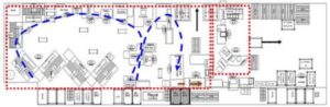
Fig 5. New Layout Line DA+VAG – Variant
Variant C
The third proposed variant is essentially the extension of the VAG line with machines from the line. Some large racks can be removed from workplace assembly VAG and can be replaced with smaller ones. In addition, supply of material for assembly is designed so that operators have the shortest routes for the material. An advantage is leaving the products for assembly line DA.
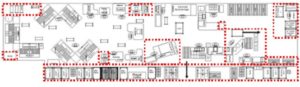 Fig 6. New Layout Line DA+VAG – Variant C
Variant D
Variant D is aimed at changing the sewing part of the production line. Wheeled carts for manipulating the material are chosen, as for variant C. These carts replace KLT boxes, and material handling is much easier. An advantage of this variant is the arrangement of the zipper sewing and bend sewing workplaces. It is possible that both workplaces can be handled by one operator depending on the number of pieces.
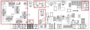 Fig7. New Layout Line DA+VAG – Variant D
Variant E
The next variant is again focused on changing the arrangement of the sewing part of the production line. Just as in variant A, finished products leave the line in only one direction. The welding machine is marked by letter L and the material is placed behind the operator. The assembly part of the production line is organized as variant C and D, but the material is placed differently.
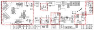 Fig 8. New Layout Line DA+VAG – Variant E
Evaluation of Variants
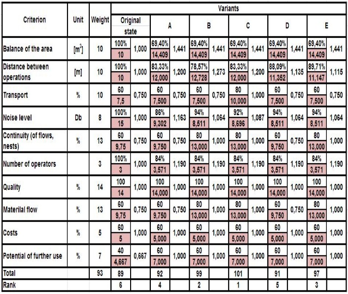
Evaluation of variants was carried out with members of the production team (operators), shift leaders, technology leaders, logistic leaders, quality managers and production planners. A multi-criteria table was created by this team.
The table is based on the methodology of multi-criteria decision approaches (described in the book by Saaty and Vargas (2006)). A difference to this method is in the values of each criterion. At the meeting, the representatives of each department (logistic, quality, planning etc.) set values for these criteria so the results may not accurately reflect values as described by Saaty and Vargas (2006). A combination of multi-criteria decision and form of brainstorming was used.
Table 1: Multi-Criteria Table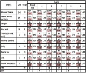
Verification by Simulation
To verify the selection of a new variant with multi-criteria evaluation, Tecnomatix Plant Simulation 9 (from Siemens) software was chosen. Tecnomatix Plant Simulation is a discrete event simulation tool which allows you to create digital models of logistic systems (e.g., production) so that you can explore the system characteristics and optimize their performance. You can use extensive analysis tools such as; bottleneck analysis, statistics and charts to evaluate or optimize production processes in a virtual environment. The main advantage of this software is that it is created for production systems in general engineering. Further advantages are simplicity, lucidity and communication with other software such as MS EXCEL, PROCESS DESIGNER etc. Tecnomatix Plant Simulation 9 is a part of the Digital factory package which we use in our department.
To compare the differences between the original state and the newly proposed variant, simulation models were made for both cases. Models contain information about the manufacturing process, such as times for operations, equipment/ machines failure, times to repair machines, unit and batch times. The model includes the routes which the operators use for transporting material between each operation. The model simulates the production of the most frequently produced products for each line.
VAG Original State Model
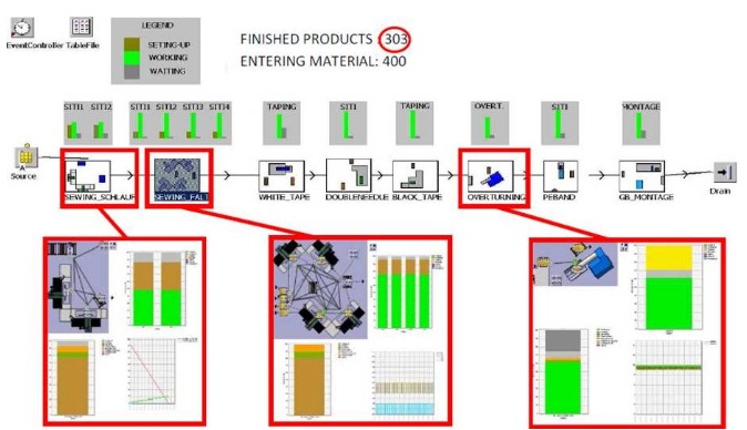
Figure 9 shows the simulation model of the VAG line in the original state. Each icon represents one workplace. On each workplace, machines with their parameters (amount of entering material, times for setting machines, working times, scraps, length of transport routes etc.) are placed. In Figure 9, you can see the amount of entering material and finished product at time T, this number is marked. You can see graphs of machine usage. We get a report from the simulation model of the original state which will be compared with the report of the new variant.
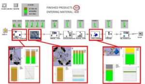
Fig 9. Simulation Model of VAG Line – Original State
DA Original State Model
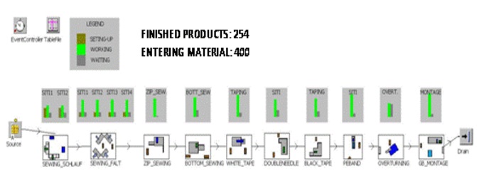
In figure 10 the number of finished products (at the time T) is marked as in Figure 9.
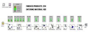 Fig 10. Simulation Model of DA Line – Original State
DA+VAG New State Model
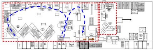
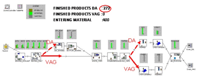
This is the simulation model of a common line. In Figure 11, you can see divided material flow from workplaces (marked by arrows). The number of finished products at time T is marked as in Figures 9 and 10. If you look carefully, you can see that there are no finished products for VAG. That is because the production process is divided into two shifts. Morning shift is for DA products and night shift is for VAG products. Figure 11 shows the first half of the morning shift. Arrows show divided material flow for products DA and VAG.
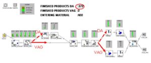
Fig 11. Simulation Model of DA+VAG Line
Conclusion
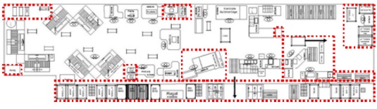
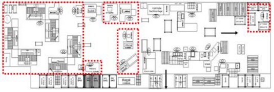
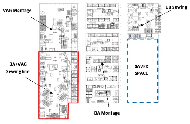
The aim of this project was to create space for a new project by merging production lines DA and VAG into one common line. The proposed variants have been assessed using a multi-criteria table, which was created by a defined team. Variant C, was evaluated as the best variant. In figure 11 you can see the space that was saved. The new production line for Audi A8 ski bag and VW T5 bag will be in this space.
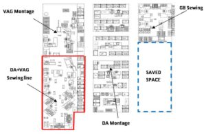 Fig 12. The CL Production Hall (New State)
A simulation model was compiled for this variant, which was to confirm the accuracy of evaluation of variants using the multi-criteria method.
In this case study advantages of simulations in a virtual environment are shown. You can try many variants of space arrangement without real movement of machines, and when you find the best variant, you can start the real project.
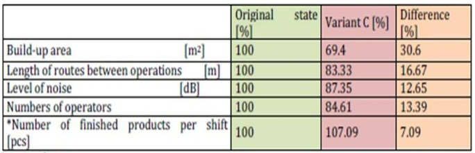
In Table 2 you can see the results from its initial state (less is better).
Table 2: Difference Compared with Original State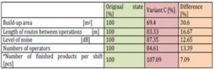
Acknowledgements
This paper was supported by the Grant Agency in the Czech Republic (GA CR). Project No. 402/08/H051: Optimizing of multidisciplinary designing and modeling of production system of virtual enterprises.
(adsbygoogle = window.adsbygoogle || []).push({});
References
Banks, J., Carson, S. J., Nelson, L. B. & NIicol, M. D. (2005). Discrete-Event System Simulation, Pearson Prentice Hall, New Jersey.
Publisher – Google Scholar
Gawron, J. V. (2000). Human Performance Measures Handbook, Lawrence Erlbaum Associates, New Jersey.
Publisher – Google Scholar
Internal material BOS AUTOMOTIVE PRODUCTS ltd.
Saaty, L. T. & Vargas, G. L. (2006). “Decision Making with the Analytic Network Process: Economic, Political, Social and Technological Applications with Benefits, Opportunities Costs and Risks,” Springer Science + Business Media, USA.
Publisher – Google Scholar – British Library Direct
Šimon, M. & Troblova, P.(2007). ‘Effective Design Aspects of Production System,’ In Annals of DAA AM for 2007 & Proceedings of 18th international DAAAM symposium, 2007, ISBN 3-901509-58-5.