Krzysztof Holak1, Hubert Adamczyk2, Daria Kawka2 and Piotr Paruch2
1AGH University of Krakow, Krakow, Poland
2Q Media Renata Adamczyk, Krakow, Poland
Volume 2026,
Article ID 946491,
Communications of the IBIMA,
10 pages,
DOI: doi.org/10.5171/2026.946491
Received date: 30 September 2025; Accepted date: 13 January 2026; Published date: 2 April 2026
Cite this Article as:
Krzysztof Holak, Hubert Adamczyk, Daria Kawka and Piotr Paruch (2026)," Optical Design of a Camera Lens for a Nanosatellite Supporting Commercial Earth Remote Sensing", Communications of the IBIMA, Vol. 2026 (2026), Article ID 946491, https://doi.org/10.5171/2026.946491
The increasing deployment of nanosatellite platforms for Earth observation creates a demand for optical instruments that combine compact form factors, low weight, and high imaging capability in harsh space environments. Previous work has largely concentrated on system integration and sensor hardware, resulting in limited guidance on the end-to-end design and qualification of photographic lenses for nanosatellites. This paper fills that gap by detailing the full optical and mechanical development workflow of a catadioptric lens intended for nanosatellite remote sensing. The optical configuration was modeled in Code V to establish essential characteristics such as focal length, f-number, and diffraction-limited resolution. A laboratory demonstrator was then manufactured and subjected to an extensive qualification program that included modulation transfer function (MTF) measurements using Imatest Master, high-temperature exposure, ultra-high-vacuum assessment, and vibration survivability testing. Following qualification, the system was integrated with the Światowid nanosatellite and launched on the Cygnus NG-11 mission to verify performance in orbit. Results from ground testing and in-flight operation confirmed stable focus, structural robustness, and imaging quality consistent with target specifications. The prototype delivered an MTF50 value of about 860 LW/PH, in line with simulation outcomes. These findings confirm that lightweight catadioptric optics can deliver thermally stable, high-resolution imagery suitable for nanosatellite Earth-observation missions and provide a validated framework for future optical payload development.
Keywords: nanosatellite optics, optical systems design, remote sensing technology.
Introduction
The design of nanosatellites and their components, including optical cameras, is conducted under strict mass and dimensional constraints (Triana, et al., 2015). This is primarily due to the limited payload capacity of launch vehicles and the high cost of sending mass into low Earth orbit (LEO). For instance, the cost of launching 1 kilogram to LEO using a Falcon 9 rocket is approximately 3,500 USD (SpaceX, 2025). Also, optical systems must be robust to launch vibrations, shocks, thermal cycling, UV exposure, and ultra-high vacuum. Materials, coatings, mechanical joints, and adhesives must be selected for space qualification. Moreover, the optics must deliver high spatial resolution and, at the same time, it must fit within the nanosatellite dimensions and adhere to standardized mounting systems (Wojtanowski, 2015, Tsitas and Kingston, 2010). Designs should minimize protrusion beyond the satellite’s envelope to be compatible with deployment mechanisms and reduce risk during launch. A key challenge in the design of optical cameras for nanosatellites is balancing image quality with constraints on mass and power. The optics must maintain focus and alignment over temperature variations in orbit. Thermal expansion, structural flexibility, and material selection must ensure that focus does not drift significantly. The environmental testing of small spacecraft often includes thermal-vacuum, temperature cycling and measuring optical performance before and after to confirm focus stability (Gadisa and Bang, 2023). Modern nanosatellite cameras, such as those provided by Dragonfly Aerospace, deliver high resolution and a wide field of view, which are essential for Earth observation missions (Dragonfly, 2023). In this paper, the authors described design and tests’ results of photographic lens for a nanosatellite used in commercial remote monitoring of the Earth. Światowid is an Earth observation satellite designed to provide high-resolution imaging, employing a Sony IMX250 CMOS 2/3″ sensor with a resolution of 5 megapixels. To achieve the highest possible ground sampling distance (GSD), expressed in meters per image pixel, the lens paired with the camera must possess sufficiently high optical resolution, an appropriately selected focal length, and relatively large aperture. This technical knowledge, combined with constraints on the lens’s maximum physical dimensions and weight limit, enables the systematic design and development of the satellite’s optical system
Optical Design of the Lens System
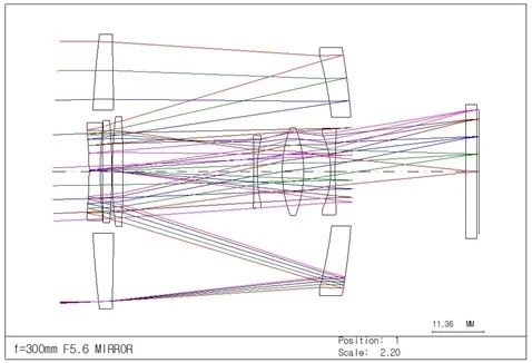
The lens optical system is based on a catadioptric design, incorporating mirrors and lenses responsible for light collection, correction of optical aberrations, and image formation on the camera sensor. Given that the f-number (aperture) of the lens determines the minimum size of the Airy disk due to diffraction limit, and considering that the optical design precludes the use of moving elements, a fixed conical aperture was implemented (Fig.1). The optical design of the Światowid nanosatellite lens was evaluated through numerical simulations using Code V software. The software produces simulation outputs in the form of optical schematics, charts, and tabular data, which can subsequently be analyzed to assess system performance. Simulations were conducted for an optical system focused at infinity, corresponding to real operational conditions for Earth observation.
Fig. 1. The optical system of the designed nanosatellite lens.
Focal length
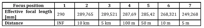
In the design specification, the focal length of the lens intended for use with the Światowid camera was decided to be within the range of 275 – 315 mm. This range ensures sufficient magnification for Earth observation while remaining compatible with the satellite’s size and weight constraints. The optical system was simulated under conditions corresponding to infinity focus using Code V software. The simulation output indicated an effective focal length (EFL) of 290 mm. This value falls within the standard tolerance commonly accepted in the photographic industry, which allows for a ±5% deviation from the nominal focal length. The results of the simulation are summarized in table 1.
Table 1. Result of simulation tests of the nanosatellite lens optical system. Focal length measurement.
Aperture (f-number)
From a photographic perspective, imaging Earth from orbit is analogous to landscape photography on the surface, with similar illumination conditions in the visible spectrum. Exposure time must be sufficiently short to prevent motion blur caused by both the satellite’s orbital speed and Earth’s rotation. Considering the lens’s field of view and orbital velocity, it was established that exposure time should not exceed 0.83 ms. Assuming that images will be captured only on the sunlit side of Earth, illumination levels expressed via the EV100 index (ISO 100, 18% gray card) range from 15 to 16 EV. Simulation of the optical system focused at infinity indicated that the effective f-number (FNO) of the system is f/4.9. The result of f-number simulation has been presented in table 2.
Table 2. Result of simulation tests of the nanosatellite lens optical system. F-number measurement.
Airy Disk Size
Another critical parameter defined in design phase is the optical resolution, expressed in terms of the Airy disk diameter. Given that the camera sensor features a pixel size of 3.45 µm and that image reconstruction requires information from at least two adjacent pixels, calculations indicate that the optical system must maintain an Airy disk diameter no larger than 8 µm to fully exploit the sensor resolution. Analysis of the simulation results indicates that the RMS diameter of the Airy disk across the entire image field ranged from 6.37 µm to 1.56 µm within desired limits.
Fixed focus mechanism for hyperfocal distance
The small dimensions and strict weight limits of the nanosatellite preclude the inclusion of a movable focus mechanism. Such a system would introduce additional energy demands and increase the risk of mechanical failure due to launch vibrations. Given the relatively stable 400 km low Earth orbit of Światowid and the infinite depth of field for terrestrial objects at this altitude, adjustable focus is unnecessary. Accordingly, the optical system is designed with a fixed focus set to the hyperfocal distance, ensuring that all targets remain within the depth of field throughout operations. The hyperfocal distance for the Światowid lens was calculated using the optical parameters: f-number f/5.6, focal length 290 mm, and target Airy disk diameter 8 µm. The results indicate a hyperfocal distance of 1878 m, yielding a depth of field extending from 939 m to infinity. This ensures that all objects beyond 939 m are recorded sharply, providing a realistic simulation of orbital imaging conditions for Earth observation.
Mechanical, Electronics and Control Design Considerations
The mass of the optical system was calculated using Code V software. Using the dimensions obtained and the density of the specified optical glass, the mass of each lens was computed. The total mass of all optical elements was 63.48 g. Maximum dimensions of the optical system were also derived. The optical path length, calculated by summing the distances between optical surfaces along the light propagation axis, was found to be 58 mm from the first to the last optical surface.
Lens mounting to the nanosatellite structure
To mount the lens within the Światowid nanosatellite, a multi-point clamping system was selected, consisting of centering screws positioned at 45° intervals around the lens barrel. This configuration allows for adjustable, stable, and concentric alignment of the lens relative to the satellite structure while minimizing mounting mass. Rear-end support and stabilization are provided by the integrated CMOS camera, which interfaces with the lens via a standard C-mount connection. The imaging sensor is based on a FLIR Grasshopper3 U3 (GS3-U3-51S5M-C) camera with a 5-megapixel CMOS sensor. The camera features a threaded C-mount interface, conforming to ANSI B1.1 standards (1-32 UN 2A). These mounting and operational assumptions ensure that the lens is securely fixed, correctly aligned, and mechanically supported during laboratory testing and orbital operation, while maintaining the strict mass limitations required for nanosatellite platforms.
Vibration resistance and mechanical integrity
Satellites are subjected to mechanical vibrations and accelerations during launch. Regardless of mission type, both the satellite and its onboard lens must comply with specified mechanical endurance criteria. For Światowid, the payload must withstand vibrations in the ranges of 5–100 Hz (2.5 G) and 100–140 Hz (1.25 G). To ensure preliminary resistance to mechanical vibrations, the laboratory prototype of the Światowid lens use threaded connections, which maintain precise alignment of optical elements along a common axis. This approach is particularly critical when integrating multiple optical groups into a single assembly. To prevent loosening of threaded connections under mechanical vibrations, all threads are secured with Loctite 271 methacrylate adhesive. This adhesive was selected due to its wide availability and NASA approval for use in hardware production for the International Space Station (ISS) (Dube and Gamwell, 2011). Research indicates that Loctite 271 exhibits high resistance to environmental stresses, including extreme temperatures (-54°C to 149°C), ultraviolet (UV) radiation, and ultra-high vacuum conditions. This approach provides confidence that the Światowid optical system will maintain structural integrity during launch and operational vibrations in orbit, ensuring stable optical performance throughout the mission.
Communication system
The communication system between the lens and the Światowid nanosatellite is designed to monitor the state of the optical assembly during orbital operations. Among various factors that can adversely affect optical performance, temperature fluctuations represent the primary challenge. Cyclic changes in solar illumination can induce thermal expansion or contraction of lenses, mirrors, and housing components, potentially leading to misalignment or deformation that compromises image quality. Due to the compact size of the lens, constrained by the nanosatellite form factor, neither active nor passive thermal management is feasible. Instead, the system aims to identify periods during which temperature-sensitive components of the optical assembly remain stable, enabling image capture under optimal conditions. Insights from the study by Rossi and Ivanow (2013) indicate that, for the SwissCube nanosatellite, cyclic solar heating caused exposed components to fluctuate between -30°C and +30°C. This range is significantly narrower than the NASA standard for spacecraft (-50°C to +150°C), reflecting the relatively slow variation in solar exposure. The lens communication system is designed to periodically monitor the temperature of the optical assembly, with particular focus on the front lens group, which is most exposed to solar heating. Temperature data allow the assessment of whether the optical system was thermally stabilized during image capture and whether it remained within the optimal operating range. These data can also help determine the best timing for Earth imaging.
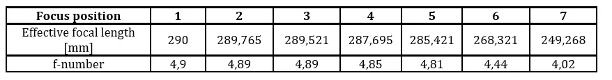
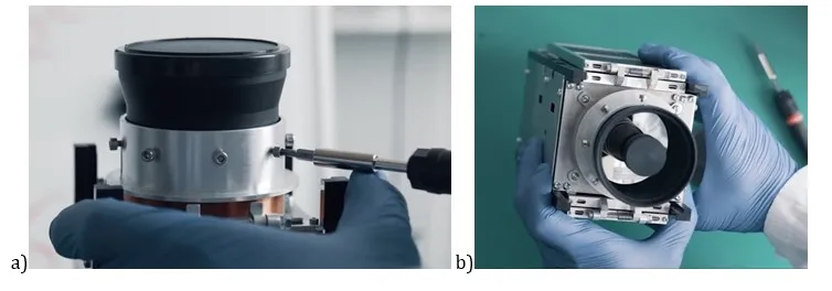
Fig. 2. The prototype of the lens for nanosatellite.
Laboratory Examination of the Lens Prototype
A series of laboratory tests have been conducted to determine the performance of all necessary parts of the assembly. The tests included investigation of resistance of the prototype (Fig. 2) to environmental conditions, such as
temperature variations and mechanical vibrations.
Temperature measurement of the optical system
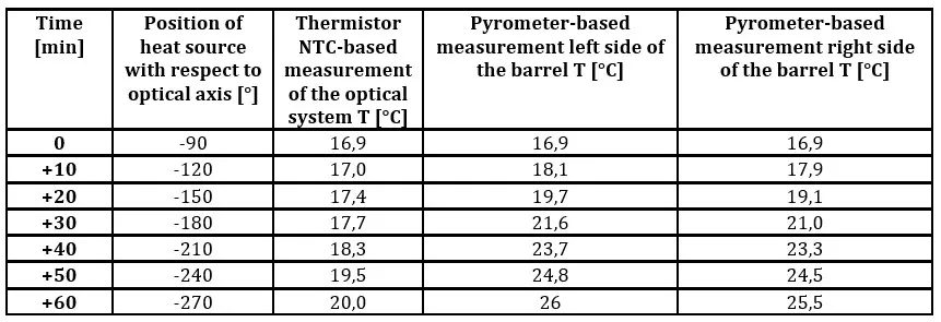
During the research phase, the optical system temperature of the Światowid lens was monitored using a miniature NTC (Negative Temperature Coefficient) thermistor. This passive sensor has a nominal resistance of 10 kΩ at +25°C and a measurement range from -50°C to +150°C. The use of an analog NTC thermistor offers several advantages, particularly in the context of integration with the onboard electronics of nanosatellites. Unlike semiconductor-based sensors, NTC thermistors (Grossi and Omaña, 2024) are robust over a wide temperature range, and their resistance variations can be easily interpreted by the onboard computer. Consequently, the lens prepared for integration with the nanosatellite is equipped with only the thermistor. For the temperature testing of the Światowid lens, the thermistor connected to the microcontroller ATMega328P placed on the Arduino Uno R3 board was positioned within the housing of the front optical group, which includes corrective lenses and the secondary mirror. This part of the lens is the most exposed to solar radiation due to its orientation relative to the Sun and its mounting within the nanosatellite structure. To simulate solar heating, a 150 W metal halide lamp was used as a heat source. Its emission spectrum closely approximates sunlight in low Earth orbit, providing realistic thermal conditions for laboratory testing. The testing procedure involved measuring temperatures at three key locations: front optical group (thermistor connected to Arduino for continuous reading), front side of the lens barrel (illuminated by the lamp), and rear side of the lens barrel (opposite the direction of illumination). In addition to the thermistor reading, the lens barrel temperatures were measured using a Benetech GM320 infrared thermometer, capable of measuring within the range of -50°C to +380°C. The three-point measurement setup enabled the assessment of both the heating rate of the optical assembly and the temperature distribution across the lens system. The results of the temperature measurements are summarized in table 3, presenting the readings obtained at each measurement location during the controlled heating procedure. Based on the obtained results, it can be concluded that the front optical group heats significantly more slowly than the lens housing due to its relatively small contact area with the surrounding mechanical elements. This thermal inertia of the front optical group provides a stabilizing effect, extending the period during which the optical system maintains a thermally stable state. In the context of orbital operation, this implies that the front optical group will remain within the desired temperature range of +20°C to +25°C for an extended duration, ensuring optimal imaging performance. The observed thermal behavior supports the assumption that periods of thermal stability will be sufficient for capturing high-resolution Earth images under low Earth orbit conditions.
Table 3. Result of lens temperature measurement.
The assembly of the lens and testing
The assembly of components comprising the laboratory model of the lens was conducted within laminar flow chambers, providing enhanced air cleanliness. During the mechanical joining of components, Loctite 271 adhesive was used to secure threaded and structural connections. At each stage of optical and mechanical assembly, optical collimators were employed to maintain the centering of lens elements within the lens barrel. These collimators ensured that the optical axis remained aligned and that the intended image quality could be achieved. The final step in the optical assembly procedure involved focus calibration, performed using a Pearl AC-500 optical autocollimator. This calibration process consisted of selecting the appropriate quantity and type of spacer shims, whose combined thickness determined the precise distance between the rear optical group and the camera sensor plane.
Optical resolution examination
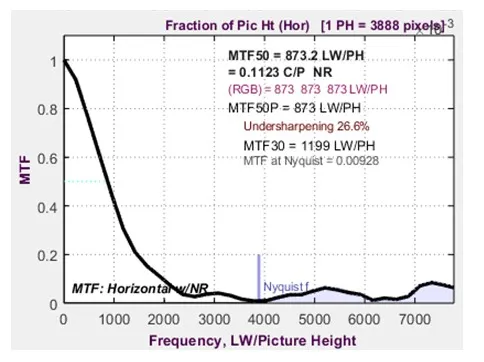
The optical quality of the laboratory lens prototype was evaluated using a computer equipped with Imatest Master software and cameras including the Panasonic GH-5 and Sony A7RII. For the tests, a 150 × 120 cm test chart was positioned at a distance of 11.23 meters from the sensor plane. Measurements were based on RAW image files. The results of these examinations yielded an optical resolution (Fig. 3) of 853 LW/PH (MTF50) on the Sony A7RII sensor and 874 LW/PH on the Panasonic GH-5 sensor. This resolution is also representative of mirror lenses with similar focal lengths, f-numbers, and catadioptric constructions, confirming that the laboratory prototype meets the anticipated optical performance benchmarks.
Fig. 3. Modulation transfer function chart for examined lens prototype.
Resistance Testing under Ultra-High Vacuum Conditions
The ultra-high vacuum of low Earth orbit, approximately 5×10⁻¹⁰ Torr, can induce outgassing in exposed components, potentially altering structural and physical properties. In vacuum conditions, heat transfer occurs only through thermal radiation and conduction between structural elements. To address these effects, optical and mechanical components, as well as bonding and assembly techniques, are selected for vacuum resistance. The resistance of the laboratory lens model to ultra-high vacuum conditions was tested at the SatRevolution laboratory in Wrocław. Prior to integration with the Światowid nanosatellite, the lens model was placed in a vacuum chamber, where it was exposed to a pressure of 2.4×10⁻⁴ mbar and subjected to temperature cycling between 80°C and 120°C over a period of 24 hours. The vacuum test was conducted in three stages: 1) 80°C, annealing duration 6 hours, 2) 100°C, annealing duration 2 hours, 3) 120°C, annealing duration 2 hours. Post-test inspections of the lens components revealed no structural changes in the materials or their connections, confirming the integrity of the assembly and allowing the lens to proceed to subsequent mechanical and optical durability tests.
Mechanical Vibration Resistance Testing
The fully assembled laboratory lens model was subjected to vibration tests. This stage aimed to ensure that the threaded connections and assembly techniques used for securing both optical and mechanical components maintained their integrity under dynamic loading conditions. The test procedure involved securing the lens model to a vibration table and subjecting it to a series of controlled oscillations. The specific frequency ranges and amplitudes applied during the test are summarized in Table 4. During the test, a total of six 60-second vibration cycles were performed for each of the ranges listed in the table. After the test, the lens’s optical performance was repeated using Imatest Master software. Resolution measurements taken before (864.2 LW/PH) and after (864.7 LW/PH) shaking pf the laboratory prototype of the lens indicate that the lens components were not damaged or changed in position, as evidenced by the unchanged calibration of the optical system. Therefore, it can be concluded that the methods used to join the lens’s structural elements proved resistant to mechanical vibration.
Table 4. Result of lens vibration tests.
High-Temperature Resistance Testing
Światowid operates in a low Earth orbit at approximately 409 km altitude, with an orbital period of 92.6 minutes. Solar irradiance at this altitude reaches approximately 1361 W/m², causing satellite components to heat up. Simulations show that unshielded lens elements may be exposed to direct sunlight for nearly 60 minutes per orbit, while, during the remainder of the orbit, the satellite passes through Earth’s shadow, allowing heat dissipation. The optical system must therefore tolerate a wide operational temperature range from -70°C to +150°C. Ultraviolet (UV) radiation in the 100–400 nm spectrum reaches the upper atmosphere and can degrade lens materials over time. High-energy UV photons may erode surfaces or alter the material structure (Azami et al., 2022). The high-temperature resistance of the laboratory lens model was evaluated in two stages. In the first stage, laboratory tests were conducted on the individual components of the lens prototype. To simulate the thermal conditions experienced in low Earth orbit, the optical and mechanical elements most exposed to solar thermal radiation were placed in an aging chamber equipped with a heat and UV light source. These components were subjected to a temperature of 80°C for 60 minutes, simulating the thermal load encountered in orbit. After completing the test, the samples were cooled to 21°C and inspected for any structural changes. Visual inspection revealed no damage or alterations to either the glass surfaces or metallic elements of the mirrors. The properties of matting coatings applied to the structural components of the lens also remained unchanged.
Integration of the Laboratory Lens Model with the Nanosatellite
The integration of the laboratory lens prototype was conducted at the SatRevolution laboratory in Wrocław. The lens model was mechanically assembled with the Światowid nanosatellite structure using a C-mount threaded connection and stabilization screws for the lens tube (Fig.4). Following assembly, the complete nanosatellite underwent a series of environmental tests, including evaluations of resistance to extreme temperatures, ultra-high vacuum, and mechanical vibrations. No damage or structural changes were observed in the nanosatellite, providing a basis for the optical system calibration test. The calibration involved capturing images of objects at distances of 2 and 3 kilometers, significantly beyond the lens’s hyperfocal distance. Analysis of the images taken with the onboard camera confirmed that the optical system was properly focused, ensuring that photographs of the Earth taken from orbit would achieve the required sharpness.
Fig. 4. Integration of the prototype lens with nanosatellite.
Orbital Deployment of the Laboratory Lens Model
The Światowid nanosatellite, equipped with the 300SR laboratory lens model, was delivered to the International Space Station (ISS) as part of the Cygnus NG-11 resupply mission. After arrival, the nanosatellite was deployed into orbit using the deployment mechanisms provided by NanoRacks. The launch was conducted aboard the Antares 230 rocket on April 17, 2019, at 22:46 Polish time (20:46 UTC) from the NASA Wallops Flight Facility in Virginia, USA. Following separation from the launch vehicle and deployment from the ISS, the nanosatellite began its operations in low Earth orbit. The orbital deployment allowed for the first in-space operational testing of the laboratory lens model under real orbital conditions, including exposure to microgravity, space radiation, and temperature cycling characteristic of low Earth orbit. These conditions provided the opportunity to validate the optical system’s performance in an environment closely replicating its intended operational use, confirming the lens design assumptions and mechanical integrity of the integrated nanosatellite system.
Analysis of Orbital Images
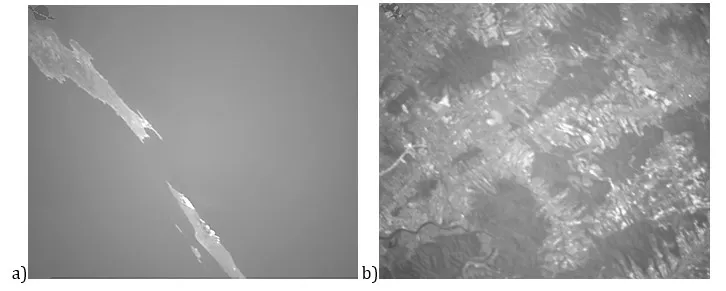
Results from the analysis indicate that the optical system successfully withstood the stresses of launch and orbital deployment, as evidenced by the proper calibration of the focus point and the high-quality resolution of Earth imagery (Fig.5a). Furthermore, no significant contrast degradation was observed in the captured images, indicating that stray light reflections within the lens tube — potentially caused by sunlight reflecting off the Earth’s surface — did not affect image quality. These findings confirm the robustness of both the mechanical assembly and the optical design of the lens system under real orbital conditions.
Fig. 5. Images captured by the prototype lens from a low Earth orbit, a) a photography of islands on the Ionian Sea, b) images showing the degradation of the image due to atmospheric phenomena. SatRevolution
Impact of the Earth’s Atmosphere on Orbital Imaging
During the analysis of orbital imagery, it was observed that one of the primary factors limiting the resolution of Earth observation from orbit is the terrestrial atmosphere (Fig. 5b). Local or widespread reductions in image resolution are caused by turbulence in air masses, an effect also noticeable in astrophotography of the night sky. Mitigating this effect is only possible through the use of adaptive optics or advanced image processing techniques. These findings highlight the external environmental constraints on imaging performance, which are independent of the optical quality or calibration of the nanosatellite lens system.
Temperature Readout during Orbital Operations
Temperature measurements of the camera sensor and the optical system of the Światowid nanosatellite were conducted during its overpasses across Europe. Some of the temperature readings were directly correlated with images captured from orbit, enabling subsequent analysis of the impact of temperature variations on imaging resolution. Preliminary analysis of the acquired data appears to confirm that short orbital period of 92 minutes limits temperature fluctuations of satellite components to a range between +17°C and +34°C, with an average temperature of approximately 26.25°C. The observed operational temperature range of the optical system remains well within standard working conditions for photographic optics. Consequently, temperature variations do not appear to induce any significant changes in the optical properties of the lens system.
Summary and Conclusions
Research on the development of an innovative photographic lens for the first Polish Earth-observing satellite was successful. The designed and manufactured lens components were subjected to simulation and laboratory testing, and the results obtained were found to be consistent with the adopted assumptions. The result of this work is a laboratory prototype of the lens (300SR test platform), which not only survived launch into Earth orbit but has also provided high-quality images to the onboard camera of the Światowid nanosatellite since the beginning of its orbital mission.
Acknowledgement
The research was conducted within the scope of the project POIR.01.01.01-00-0529/18 financed by the National Centre for Research and Development in Poland.
References
Azami, M. H. B., et al. (2022), ‘Design and environmental testing of imaging payload for a 6 U CubeSat at low Earth orbit: KITSUNE mission, Frontiers in Space Technologies, 3, 1-16.
Dube, M.J. and Gamwell,W.R. (2011), ‘Performance characterization of Loctite® 242 and 271 liquid locking compounds (LLCs) as a secondary locking feature for International Space Station (ISS) fasteners’, National Aeronautics and Space Administration, Langley Research Center. [Online], [Last accessed October 27th 2025], https://ntrs.nasa.gov/api/citations/20110011064/downloads/20110011064.pdf
Gadisa, D. and Bang, D. (2023) ‘Small Satellite Electro-Optical System (EOS) Technological and Commercial Expansion’, Acta Astronautica, 213, 355-372.
Grossi, M. and Omaña, M. (2024) ‘Accuracy of NTC Thermistor Measurements Using the Sensor to Microcontroller Direct Interface’, Engineering Proceedings, 82(12), 1-8.
Rossi, S. and Ivanov, A. (2013) ‘Thermal model for cubesat: A simple and easy model from the Swisscube’s thermal flight data’, International Astronautical Conference, Beijing, China, 23-27th Septmeber, 2013.
SpaceX Falcon 9 Technical Information (2025), [Online], [Last accessed October 27th 2025], https://www.spacex.com/vehicles/falcon-9/
Triana, J.S., Bautista, S. and Díaz González, F.A. (2015) ‘Identification of Design Considerations for Small Satellite Remote Sensing Systems in Low Earth Orbit’, Journal of Aerospace Technology and Management, 7(1), 121-134.
Tsitas, T.S. and Kingston, J. (2010) ‘6U CubeSat design for Earth observation with 65m GSD, five spectral bands and 14Mbps downlink’, The Aeronautical Journal, 114 (1161), 689-697.