Electrical Engineering, Instrumentarion Laboratory, Federal University of Rio Grande do Sul, Porto Alegre, Brazil
Volume 2013 (2013),
Article ID 113945,
Research in Neurology: An International Journal,
15 pages,
DOI: 10.5171/2013.113945
Received date: 2 March 2013; Accepted date: 3 April 2013; Published date: 28 April 2013
Academic Editor: Wei Yen Hsu
Cite this Article as:
Michel Carra and Alexandre Balbinot (2013), "Sensorimotor Rhythms to Control a Wheelchair," Research in Neurology: An International Journal, Vol. 2013 (2013), Article ID 119574, DOI: 10.5171/2013.119574
This paper shows the development of a non-invasive BCI system using brain signals from somatosensory cortex. The acquisition of signals was performed using one electrode cap in accordance with 10-20 system and using 3-channel EEG in order to command a motorized wheel chair without involvement of peripheral nerves and muscles. Two experiments were carried out with untrained volunteers performing imaginary two movements, and several aspects are evaluated, such as the method of selection and feature extraction, hit rates classification, application of a database for comparison, as well as the general evaluation of the system. Hit rates (average) of 74.9% were obtained from the three best volunteers of the experiment with two movements. In the experiment with the wheelchair, 65.7% hit rates (average) were obtained for two directions, respectively.
About six decades after invention of EEG, studies have emerged using brain signals to control devices and this area became known as BCI (Brain-Computer Interface) or BMI (Brain-Machine Interface). Wolpaw et al (2002) mentioned that brain activity produces electrical signals that can be detected in a non-invasive or invasive way, and BCI systems can translate these signals into commands, which allow communication with devices without involvement of peripheral nerves and muscles.
Typically non-invasive BCI systems use brain activity obtained from the scalp (usually using EEG) and are able to allow basic communication and control for people with severe neuromuscular disorders (Birbaumer et al (2003) and Sellers et al (2007)). Some studies with invasive BCI systems use records from neuronal action potential or local field potential directly in the cerebral cortex or near the surface- the vast majority of these studies is still restricted to monkeys (Chapin et al (1999), Wessberg et al (2000), Serruya et al (2002), Taylor et al (2002) Carmena et al (2003), Pesaran et al (2002), Leuthardt et al (2004) and Hochberg et al (2006), because they involve surgical techniques and clinical risks- the electrodes are implanted in the cerebral cortex for long periods and can cause infections and other injuries to the brain. In general, BCI system allows interaction of some subject with the external environment, through the conscious control of his thoughts and not by muscle contractions as, for example, inhuman-machine interfaces controlled or managed bymyoelectric signals (Sellers et al (2007)). In a BCI system, the data acquired by EEG should be processed in real time to be able to get signals for controlling devices. In general, BCI system is composed by brain signals acquisition and pre-processing, and extraction of significant features followed by their classification. The result of classification allows controlling signals from external devices (Kubler and Muller (2007)). In summary, any project involving BCI system requires an efficient signal processing that includes pre-processing, extraction, and classification steps.For example, Liangetal. (2006) emphasize the classification stage, including a good summary of linear methods, Markov chains, among others. Like any communication system or control, BCI system has inputs (e.g., the electrophysiological activity of the user), outputs (e.g., commands to external devices), components that convert input(s) into output(s) (signals processing), and protocol, which determines the start, end, and operation time (Wolpaw et al (2002)).
Another characteristic found in BCI systems is that the user receives stimuli (visual, auditory or tactile) and/or performs mental tasks while their brain signals are captured and processed. According to the stimulus/tasks performed by the volunteer, a series of phenomena or behaviours extracted from EEG signals can be detected, such as the Slow Cortical Potentials (SCPs), Sensorimotor Rhythms (SMR), Event-related Potentials(ERP), and Visual Evoked Potentials (VEPs). Further details of these phenomena or behaviours can be found in Kubler and Muller (2007).
It is known that, since the EEG discovery in 1930, certain events can block or desynchronizing normal brain activity in determined frequencies and these changes can be detected by analyzing the signal frequency (Pfurtscheller et al (1999)). As a consequence, events related to some phenomenon can also be represented by frequency changes in brain activity, or, in other words, can be represented by energy decrease or increase in a frequency band. Energy decrease in a frequency band is called ERD (Event-Related Desynchronization) and elevation is called ERS (Event-Related Synchronization). SMR is usually divided into two frequency bands, μ band (8-12 Hz) and β band (13-30 Hz), and are quantified in form of ERD or ERS.
Many factors suggest that μ and/or β rhythms can be good signs to be used in BCI systems. They are associated with cortical areas more directly linked to brain motor activity (Wolpaw et al (2002)). Furthermore, it was verified that the SMR occur both at the movement realization as in its imagination (McFarland et al (2003)), and may help people with severe disabilities to perform tasks only with the movements’ imagination, after receiving a proper training. The preparation and realization of imaginary movement is accompanied by ERD effect, while approximately 1s after the imagination task’s ending, the ERS effect occurs. In the case of imaginary movement of the hands, the ERD effect occurs with greater intensity on the contralateral side of imaginary movement, while the ERS effect occurs with greater intensity on the ipsilateral side of the movement (Pfurtscheller and Neuper (1997), Pfurtscheller and Neuper (2001) and McFarland (2008)). Considering the amount of current publications, it is possible to affirm there is a great interest in research involving BCI systems and other devices involving assistive technology. Therefore, to contribute to this area, this work presents the development of a non-invasive experimental BCI system, using EEG and an electrode cap to capture the brain signals of somatosensory cortex, thus allowing the analysis of Sensorimotor Rhythms (SMR).
Based on analysis of brain signals (F3-P3 and F4-P4) commands are generated to move a motorized wheelchair. Two experiments were carried out during this work, evaluating aspects related to the method of selection and characteristics extraction, classification of hit rate, hit rate during the experiments, and overall evaluation of the developed system. In addition, the international database (BCI Competition II (2003)) was used, thus allowing a comparison of results obtained.
Methods Equipment and Materials
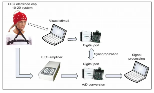
The proposed experimental BCI system is shown in Figure1. This system consists of an EEG, a head cap with tin electrodes (Jasper (1958)), elastic, special conductive gel made for EEG, a computer to generate visual stimuli, two data acquisition boards, and a computer for acquisition and processing EEG signals.
Figure 1. Block Diagram of Proposed Experimental System
In this study, two bipolar EEG channels were used to capture the brain signals from somatosensory cortexatF3-P3 and F4-P4 locations. The analog gain was set to 20000. For analog-to-digital conversion, a National Instruments USB6008 board was used at a sampling rate of256Hz. Bio signals acquisition and processing are performed with Lab View 9.0 integrated with Matlab software.
Basic Steps for Signal Processing
The techniques used for processing digital signals are shown in this section. This processing can be divided into three basic steps discussed below, namely selection of specific parameters, features extraction, and classification.
Selection of Specific Parameters
Two analyzes were performed in this step: (1) determining the most relevant frequency bands for each volunteer and (2) verification over time the variation of bands energy of selected frequency in order to identify temporal localizations, where significant differences of energy occur in the somatosensory cortex region. The selected parameters are used in features extract stage, aiming to extract the most relevant features for each user, and consequently achieve the highest hit rate in the classification stage.
Each individual may show EEG signs with specific frequency bands, both in μ band (8-13Hz) and β band (14-30Hz), and, therefore, to perform this process becomes indispensable. The method developed analyzes the μ band and β band separately by selecting the most relevant components and that form a frequency band with at least 3 components, such as 10 to 12 Hz. One relevant band is selected in μ band and other one in β band. The selection of bands is based on analysis of the relevance values of each frequency component. This method analyzes the components of μ and β zones separately, selecting the most relevant components, and forming a band with frequency of at least 3 components. Several tests were performed to validate this method of automatic selection of relevant bands.
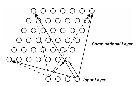
In this study, the method based on non-linear classifier LVQ (Kohonen (1990)) was used (100 replicates were performed LVQ algorithm. Studies showed that 100 repetitions presented a cost-effective (good computational performance)). The system known as a Kohonen Network has a fee-forward structure with a single computational layer of neurons arranged in rows and columns. Each neuron is fully connected to all the source units in the input layer, for example, the outline of Figure 2.
Figure 2. The Architecture a Self-Organizing Map (SOM): A One Dimensional Map
The aim is to learn a feature map from the spatially continuous input space, in which our input vectors live, to the low dimensional spatially discrete output space, which is formed by arranging the computational neurons into a grid. The stages of the SOM algorithm that achieves this can be summarizes as follows:
(a) Initialization: choose random values for the initial weight vectors wj;
(b) Sampling: draw sample training input vector x from the input space;
(c) Matching: find the winning neuron I(x) that has weight vector closest to the input vector; i.e.; the minimum value of dj(x)=∑iD=1)(xi-wji )2 ;
(d) Updating: apply the weight update equation ∆wji=η(t)Tj,I(x) (t)(xi-wji ), where Tj,I( x) (t) is a Gaussian neighborhood andη(t) is the learning rate;
(e) Continuation: keep returning to step 2 until the feature map stop changing.
The using a SOM is to encode a large set of input vectors {x} by finding a smaller set of representatives or prototypes or coded-book vectors {WI(x)} that provide a good approximation to the original input space. This is the basic idea of vector quantization theory, the motivation of which is dimensionality reduction or data compression. In effect, the error of the vector quantization approximation is the total squared distance:
Between the input vectors {x} and their representatives {WI(x)}. We shall see that performing a gradient descent style minimization of D does lead to the SOM weight update algorithm, which confirms that it is generating the best possible discrete low dimensional approximation to the input space (as least assuming it does not get trapped in a local minimum of the error function).
The LVQ is a supervised version of vector quantization that can be used when we labeled input data. This learning technique uses the class information to reposition the Voronoi vectors slightly (a vector quantizer with minimum encoding distortion is called a Voronoi quantizeros nearest-neighbour quantizer), so as to improve the quality of the classifier decision regions – it is a two stage process (see Figure 3). The first step is feature selection — the unsupervised identification of a reasonably small set of features in which the essencial information content of the input data is concentrad. The second step is the classifications where the feature domains are assigned to individual classes. The SOM algorithm provides a useful method for computing the Voronoi vectors (as weight vectors) in an unsupervised manner.
Figure 3. Relationship between the SOM and LVQ
The basic LVQ approach is quite intuitive. It is based on a standard trained SOM with input vectors {x} and weight/Voronoi vectors {wj}.The new factor is that the input data points have associated class information. This allows us to use the known classification labels of the inputs to find the best classification label for each wj, i.e., for each Voronoi cell. The basic LVQ algorithm is a straighforward method for shifting the Voronoi cell boundaries to result in better classification. It starts from the trained SOM with input vectors {x} and weight/Voronoi vectors {wj}, and uses the classification labels of the inputs to find the best classification label for each wj. The LVQ algorithm then checks the input classes against the Voronoi cell classes and moves the wj appropriately:
(a) If input x and the associated Voronoi vector/weight wI(x) (i.e. the weight of the winning output node I(x)) have the same class label, then move them closer together by ∆wI(x)(t)=β(t)(x–wI(x) (t)) as in the SOM algorithm (where β(t) is a learning rate that decreases with the number of iterations/epochs of training. In this way we get better classification than the SOM alone.);
(b) If the input x and associated Voronoi vector/weight wI(x) have the different class labels, then move them apart by ∆wI(x) (t)=-β(t)(x–wI(x)) (t));
(c) Voronoi vectors/weight wj corresponding to other input regions are left unchanged with ∆wj (t)=0.
In the first step of this algorithm, the relevance average of each frequency component among used EEG channels is performed. In the band selection, parameters (maximum, minimum, and span) of all analyzed frequency components are used. These parameters are used to determine the thresholds used in the automatic selection method.
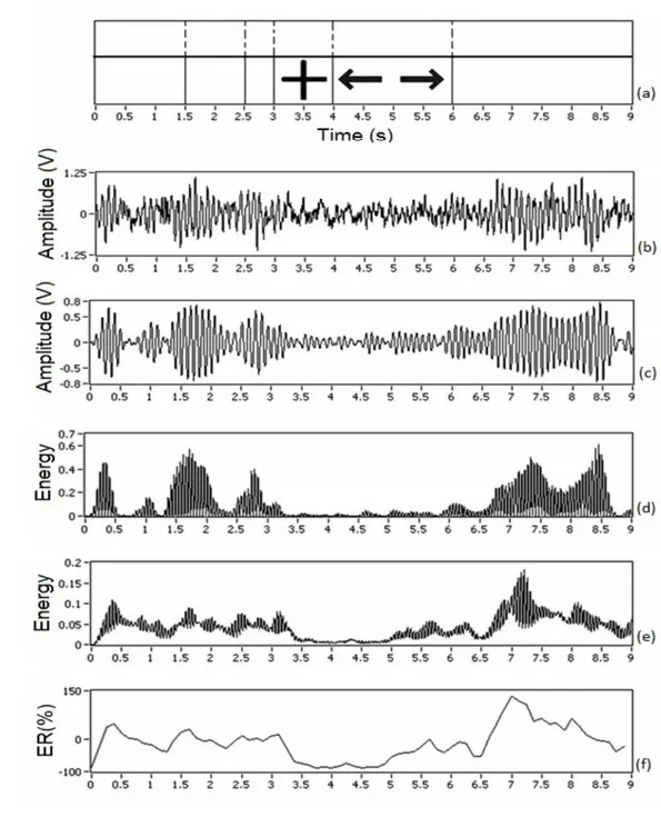
After selecting the most relevant frequency bands for each volunteer, it becomes necessary to analyze the energy variation in each selected band. According to experiments conducted in this work, it is possible to increase the hit rate of the classification process up to 15%, by extracting features from temporal localizations, where there is a greater energy difference among the capture sites of the brain signals in the region of the somatosensory cortex during stimuli presentation. The method of bands energy (Band Power Method or BPM) was used for this evaluation (Schloegl et al (1997)) and this energy difference was analyzed using the Lateralization Index (LI). The LI is useful to evaluate the occurrence of ERD or ERS in contralateral side of the movement – effect called lateralization (Graimann and Pfurscheller (2006)). To facilitate the understanding of BPM method, Figure 4 shows a graphical example. In this example, 20 tracks were used (random stimuli to the right or left side — see Figure 4 (a)) of an experiment conducted with G1. In this test, the volunteer should perform the imaginary movement of closing his hand to presented stimulus.
Figure 4. Graphical Example of BP Method – G1 Volunteer Data
The stimulus is presented to volunteer between 4-6s of each track. The Figure 4 (b) shows the raw EEG signal (channel F3-P3) of track number 16. In Figure 4 (c), band-pass filtering (fc = 8-12 Hz, filter of 2nd order Butterworth type) is performed, and in Figure 4 (d) the filtered signal is squared, that is, the values of signal energy are obtained. In Figure 4 (e), the arithmetic mean of energy of all 20 tracks of this experiment is performed and finally in Figure 4 (f) the Relative Energy to the reference period is obtained. After approximately 500 ms of the stimulus disappearance (at 6.5s instant) elevation in ER occurs, i.e., the ERS effect occurs.
Features Extraction
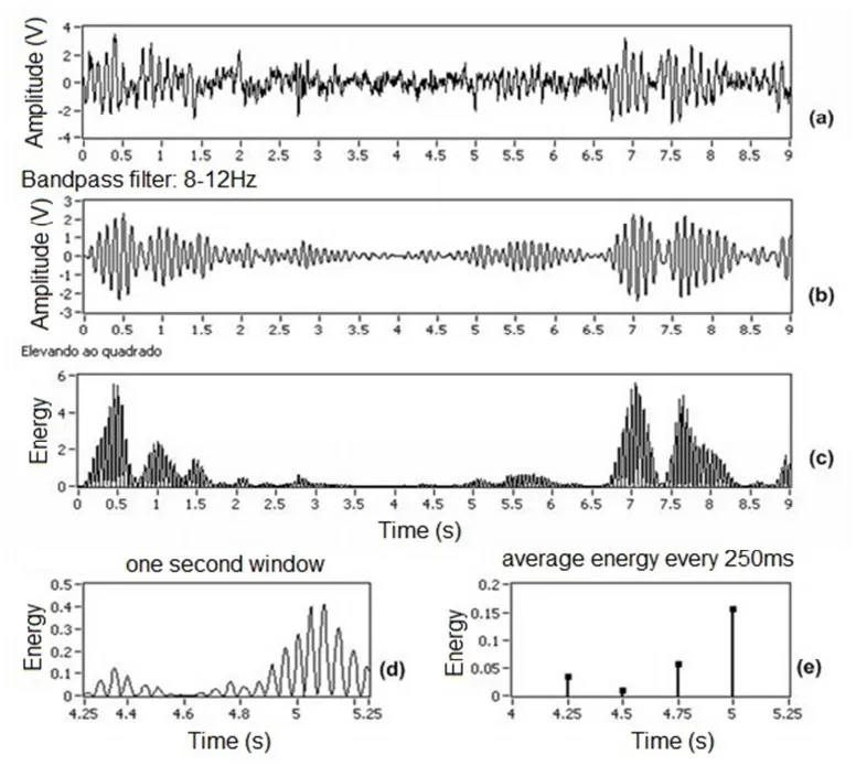
This section shows the method used for feature extraction based on spectral parameters by quantifying the energy of a determined frequency band. The energy quantization of a determined frequency band is accomplished by following these steps: (1) selecting a frequency band using band-pass filtering; (2) raising the amplitude to square in order to obtain the energy of the selected frequency band; (3) Cutting a window of 1 s from the track in question; (4) compressing the number of samples of the cutting window at CR rate, obtaining y energy values according to Equation (2):
In which ta is the sampling rate in Hz, ct is the track length in s, and y is the number of desired samples.
In this work, CR = 64 and y = 4 were selected for a sampling rate of 256 Hz. This means that the samples are compressed at a rate of 64 times (one energy value every 250ms) using the arithmetic mean as reduction method. In experiments performed with two EEG channels, 16 features (2 EEG channels x 2 frequency bands x 4 energy values) are extracted and classified. Figure 5 (a) shows the normalized raw signal from a track (chosen at random — duration of 9s) of an experiment conducted during this work. Figure 5 (b) shows the same filtered signal between 8 and 12 Hz, and Figure 5 (c) shows the squared amplitude, obtaining energy. In Figure 5 (d), a window of 1 s is extracted; in this case, as example, the extraction is started at 4.25s instant. Figure 5 (e) shows the final step in the extraction process, making up the arithmetic average every 250 ms, resulting in 4 characteristics.
Figure 5. Method of Features Extraction: (a) Normalized Raw Signal, (b) Band-Pass Filtering 8-12 Hz, (c) Squared Amplitude, (d) Window of 1 s Clipped of Signal and (e) Average Energy Every 250 ms
Features Classification
In general, the conversion of user’s intention is performed at classification stage (expressed by features extracted from brain signals) into command signals for an output device, for example, a motorized wheelchair. In this work, the features classification is performed using Linear Discriminant Analysis method that is one method widely used in BCI systems (Blankertz et al (2007)).
Experimental Protocol
All tests were accompanied by a system operator, whose function was to put the electrodes cap on the volunteer, enter the conductive gel in the cap electrodes and connect all equipment to be used. Furthermore, the system operator guided the volunteers to the tasks to be performed; for example, he asked them to carry out some test tracks in order to become familiar with the experiment. All volunteers agreed to participate in the experiments.
Experiment 1: Two Imaginary Movements
In experiment 1,240 tracks for each volunteer are presented, divided into 3 sections of 80 tracks performed in different days or shifts. The total time for each section is approximately 20 minutes. The specific parameters of each volunteer were obtained with data of the first 25 tracks of each section, and the data classification is made for the 55 remaining tracks. In this experiment, five healthy males were involved (R1, W1, B1, M1, and G1 volunteers) with a mean of (25.6 ± 9.1) years old, who did not have any contact with BCI experiments at lifelong.
In each track, the volunteer receives a visual stimulus represented by an arrow (in 2D), indicating direction to the right or to the left side. During the presentation of this arrow, the volunteer must only imagine the closing movement of one hand (as if squeezing a ball) on the same side that the arrow points. The order of the arrows selection is completely at random, following a uniform distribution. The volunteers had not received any feedback during the experiment, i.e., there was no generation of commands to control an output device. Each track has a length of 9s, with a random interval from 2 to 5s with the following temporal order: 0-3s: reference period, the screen remains in blank; 3-4s: a symbol representing a cross appears on the screen, along with an audible warning (“beep” sound at a frequency of 400Hz); 4-6s: 2D arrow appears indicating the side that the volunteer must imagine the closing movement of the hand; 6-9s: the post-movement period, screen in blank.
Before the experiment, the volunteers performed around 10 to 20 test tracks to be familiarized with the experiment. All volunteers were asked to keep always the maximum attention in performing the experiment. In this experiment, two EEG channels localized in F3-P3 and F4-P4 were used, 16 features on each track were extracted and classified, and the LI method for energy analysis was applied.
Experiment 2: Interface with a Wheelchair
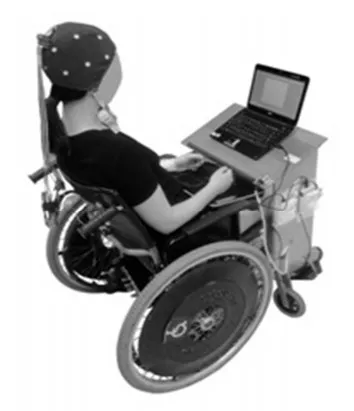
In the experiment 2, the system interface used in the Experiment 1 with an output device is performed, in which, commands are generated to move a motorized wheelchair. The volunteer performs the experiment tasks sitting in a wheelchair as illustrated in Figure 6.
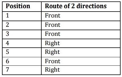
In experiment 2, 50 tracks are presented to the volunteer, and these data are used for classifier training and to obtain the specific parameters of the volunteer. Afterwards, the volunteer must complete a route of 7 predetermined positions for 3 times, with the minimum possible tracks. Only one volunteer (female, 30 years old, L1 volunteer) participated in this experiment, and she had already participated in BCI experiments throughout this work. In the course of two directions, arrows to the right and forward are presented, and the volunteer should make the imaginary movement of the foot (front arrow) and right hand (right arrow). Table 1 shows the route order of 7 directions.
Figure 6. Illustration of the Volunteer Sitting in a Wheelchair during the Experiment 2
Table 1: Course Order of the Experiment 2
The stimuli presentation is exactly equal to that of Experiment 1, in which the classification and generation of command to move the chair are held shortly after the end of the corresponding track. In the course of two directions, the arrow to the left is not presented in both the training and the completion of the route. After presentation of 50 training tracks, the volunteer parameters are selected (procedure that takes about 5 minutes and is performed by the system operator) and then the presentation of the first series of corresponding route stimuli starts, and the chair will go in direction to the stimulus only if the classification result of the corresponding track is correct. Otherwise, the chair will remain standing in place, and the same stimulus will be presented to the volunteer at the next track. The process is repeated until the classification is correct. The idea is that the route is completed with the smallest possible number of tracks and consequently in the shortest time. At the end of the first series of the corresponding route stimuli, the chair is taken to the starting point of the route for performing the second and third series of the corresponding route. In this experiment, 3 EEG channels localized in F3-P3, Fz-Pz, and F4-P4 were used and 24 features on each track were extracted and classified.
Results Results of the Experiment 1
Five volunteers (R1, G1, M1, B1, and W1) underwent three sections of 80 tracks, except the first section of B1 volunteer with 60 tracks. It was noted that for all volunteers α is the most relevant frequency band, and, therefore, it was selected for carrying out the analysis of energy for determining the window localization of the features extraction. The limits of α-band (8-13 Hz) are selected with the automatic method presented in this work.
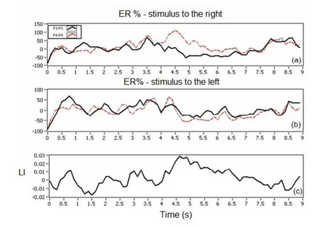
The Figure 7 shows the graphical result of RE (or ER) of the stimuli to right, left, and LI from the section in which the best classification result for each volunteer was obtained. It is possible to note that R1 volunteer shows the typical behavior of SMR, in which the ERD effect occurs more strongly on the contralateral side to the movement, and in this case it is expected that this volunteer get better hit rates than the remaining volunteers.
Figure 7. Graphical Results of Energy Analysis of R1 Volunteer, Section 2 (a) RE Stimulus to the Right, (b) RE Stimulus to the Left and (c) LI
The specific parameters of each volunteer were also adjusted manually (by visual analysis) as other works (Haselsteiner and Pfurtscheller (2000) and Coyle et al (2005)) to compare the results with parameters selected automatically. Table 2 shows the average hit rates for each volunteer as well as the general hit rate. Taking into account the results obtained by manual adjustment, the overall hit rate found for the right stimuli was 72.3% and 70.5% for the left ones.
Table 2: Hit Rate Average for Each Volunteer and Overall Average
Results Using BCI Competition II, Data Set III
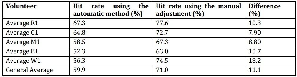
In this study, data from the BCI competition II, data set III were used in order to apply the method employed in this work to a database already known, allowing comparison of results obtained by other competition participants. Table 3 shows the found hit rates, using both the automatic method for selecting parameters such as performing manual parameters adjustment, as well as the hit rates average.
Table 3: Hit Rates Using Selected Parameters with Automated Method or Adjusted Manually
The hit rates of volunteer from BCI competition were higher than those found in experiment 1 conducted in this work. The graphs used in the specific parameters selection already indicated that high rates could be found, because this volunteer can control his brain rhythm, enabling high differentiation between the two classes as shown by graphs of energy analysis. Most likely this volunteer was very well trained to perform the experiment, and the database was generated in a controlled environment. The results obtained with the method of this study were very close to the best results obtained by other researchers; the first five placed in the competition found hit rates between 82.9 and 89.3%[19], demonstrating the functionality of this work method.
Results of Experiment 2
One volunteer (L1) participated in the experiment. Results are presented and discussed below. Table 4 shows the hit rates found in each series of the route of 7 positions held with the wheelchair.
Table 4: Hit Rates Found in Each Series of Experiment 3
Discussion about the Experiments Results
For example, in Experiment 1, maximum hit rate of 83.6% was found; other’s papers (Schloegl et al (1997), Haselsteoner and Pfurtscheller (2000) and Coyle et al (2005)) report some results up to 90.0%, but in this work 74.9% of hit rate was found, considering the average of the 3 best volunteers of the Experiment 1, that is a result compatible to one reported by Pfurtscheller et al. (2001). It is very important to mention that there is not feedback or control on the imaginary tasks performed by volunteers, and there is no way of knowing if the volunteer performed the task correctly, if he was distracted, or if he was physically or mentally tired. Furthermore, the location of this work tests had a lot of noise outside (room located next to a busy street) that might distract the volunteer, and, therefore, it is not a controlled environment. This fact can be considered as a positive point, because the environmental conditions of the experiments are close to real life.
Another very important point is the question of the volunteer himself. The comparison made with the data of BCI competition II leave no doubt on this point, by which an average percentage of 88.2% hit rate was found, a percentage very close to the best result of the competition. This proves that the method employed in this paper works and it is possible to achieve high hit rates. Results found in the selection of specific parameters of volunteer from BCI competition II, data set III show an excellent performance of SMRs of this volunteer, i.e., with frequency bands very well defined. This is most likely linked to an extensive training carried out with this volunteer. All volunteers who participated in this study did not have any experience with BCI experiments and only some of them showed the expected SMRs behavior in accordance with the experiment temporization, and thus may have presented results below expectations.
With respect to methods of selecting specific parameters used in this study, better results were found when the manual adjustment of parameters were performed, determined by the system operator/expert. Automatic methods still cannot replace the expert, according to results found in this work and others (Schloegl et al (1997), Haselsteoner and Pfurtscheller (2000) and Coyle et al (2005)). Using automatic methods introduced in this work, worse results were found compared to manual adjustment (difference of 11.1% on average hit rate in Experiment 1).
Finally, the results from Experiment 2 were consistent with the results obtained in this work. In this experiment, it was noted that feedback to the user is an important factor for the volunteer to keep attention on the experiment, and consequently improve the hit rate.
Conclusions
The proposed system had as main goal to develop a brain/computer interface based on the achievement of an imaginary volunteer movements, in which their brain signals in the region of the somatosensory cortex are acquired by using EEG with 3 channels, performing a series of tests for the system to command output devices. Results obtained in this work are close to those found in the literature as well as to interface with a motorized wheelchair with an experimental portable and low cost system, controlled only through brain signals captured by EEG. It is very important to mention that all tests were performed in uncontrolled environment, with portable and low cost equipment, thus enabling a future interface with real-life situations, since our research group believes to be possible the development of BCI systems applicable to everyday life.
It was noted that not all volunteers behaved as expected in their SMRs, indicating that the system needs to be adapted at maximum to user, in order to obtain the best possible results. The proposed method showed good results in all experiments, even when tested with BCI competition database, proving to be a simple and intuitive method and highly adaptable to the user.