Introduction
Nowadays the vacuum-tubes type represents undoubtedly the leading technology of solar collectors with more than 90% of worldwide market, which is strongly concentrated in cold high-latitude developed countries. There, these collectors are preferred since they receive twice solar irradiation along the day than flat ones and minimize heat losses as well. Large sizes of markets and local manufacturing allow users to get prices down 500 USD for a single-family unit. However, the scenario is almost opposite in developing countries, where final prices can easily triplicate the previous one and also there are many other social-economic barriers, as it was already discussed [1].
On the other hand, the local manufacture of low-cost collectors could be a good choice for satisfying the domestic demand in developing temperate and tropical countries, regarding the low temperature difference involved. Recently we have proposed the use of both, low-cost plastic materials universally available and a simple and robust design in order that these units could be home-made built following a modular concept. This way, many barriers (like costs of freight and technician installation, risk of breakage, concerns about actual performance of collector, etc.) can be avoided.
The basic design proposed consists of a long large-diameter LDPE black hose connected directly between district-grid water supply and consumption, which is wrapped with a transparent plastic glazing and is simply resting onto the roof. Although this concept has been maybe in mind of every solar enthusiastic, its right design implies many challenges. By means of hydraulic and thermal modeling, this system has already demonstrated to work well in tropical low-latitude countries [1]. However, despite its good ability for collecting solar irradiance during the day according to the water-pond characteristic [1,2,3,4], its overall performance is poor due to its strong nocturnal cooling and so it is not recommended for temperate locations.
In this paper and by means of a fully thermal modeling we have focused in optimizing this design so that it can be applied to temperate and cold medium-latitudes climates. The particular characteristics of this kind of collectors are realized and a comprehensive thermal analysis was performed. This way, the roof tilt angle, hose diameter and quality of plastic glazing are optimized for different ambient conditions, showing that its performance can be noticeably enhanced in order to work well in temperate climates.
Hydraulic Modeling
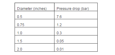
The hydraulic behavior must be checked to assure the consumption flow desired; for example a thin long hose could be preferred to increase the solar surface, but this way the hydraulic restriction increases and a too low flow could be obtained. This modeling was performed in the previous work and is summarized here [1]. Table 1 shows the grid pressure required for supplying an average consumption flow (20 l/min) according to the diameter D of a 100-meter length hose. Here, is shown that diameters larger than 1” can fit the desired flow working on modest pressures or conversely, thinner hoses lead to very low flows. This last is ultimately the reason why most of empirical collectors built on this simple design have failed.
For illustrating this key point, let us consider a standard flat collector working between a collecting unit and a storage tank, in which the heating coil is built by means of a long ½” 100-m plastic hose as Figure 1 illustrates. The difference of densities between both lengths is the only driven force of this natural-convection circuit and it can barely pump the cooling flow; for example, for 40°C and 1.5m height the buoyancy pressure is just 2cm of water column. This boundary condition explains the traditional grid-type design for the heating coil, but this way the advantages of plastic tubes are precluded [1]. Hence, the use of a long single coil causes its dangerous overheating and a negligible flow to tank, leading to a very poor performance. In this sense, although the use of district grid pressure is a good choice (it is 500 times greater than buoyancy) the hydraulic behavior must be considered. Therefore, diameters above 1” are recommended for using a single long line, or instead the use of multiple parallel lines is mandatory.
Table 1. Minimal Pressure Grid Required for Obtaining Average (20 L/Min) Flow
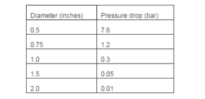
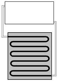
Figure 1. Scheme of Flat Solar Collector Having a Single Coil
Thermal Modeling
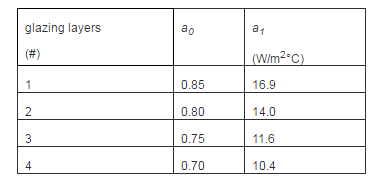
The thermal behavior along the day is described by its dynamic modeling, which was fully performed in our previous work [1]. For a north-oriented cylinder, the normal solar flux (In) along a given day can be calculated relating to the altitude solar angle (α) and roof tilt angle (β). From here we can calculate the “ideal” (that is, considering constant solar flux) solar power received and thus, the energy absorbed and the heat losses by considering the characteristic efficiency function of collector. Hence, the dynamic energy balance is used to determine the temperature along the day [1]. This model allows us to simulate the thermal daily transient according to parametric data: 1) both parameters of the efficiency function: a0, the optical efficiency, and a1, the heat-losses parameter; 2) the daily total irradiance G”(estimated from solar charts); 3) the daily cycle of ambient temperature, defined by their mean value and peak-to-mean variation. Note that the qualities of glazing and thermal insulation (that ultimately define the quality of collector) are both defined by their efficiency parameters (a0, a1). So, it is a key to characterize by testing these parameters in order to optimize the performance of collector, since all others parameters used for optimizing (the hose diameter and the tilt angle) can be estimated from modeling.
Experimental Study
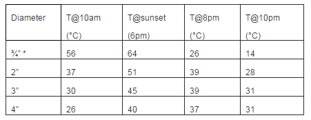
A set of preliminary tests were performed in order to fit the collector’s parameters. Several short sections of 1-meter length were tested on vertical position during perfectly sunny days in Salta, illustrated in Figure 2. The solar flux was measured with a Seaward 200R solar irradiance meter and the temperature signals were performed with K-type thermocouples. Both parameters are fitted by non-linear regression with 10% error bandwidth and are shown in Table 2. The a0 is fitted by considering the initial growing rate of heating and after that, the value of a1 is adjusted by considering the peak of temperature and the cooling rate during the night (when a0=0).
Table 2. Fitted Parameter of the Collector for Different Number of Insulative Layers
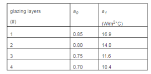
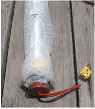
Figure 2. Photo Illustrating the Double Glazing LDPE 1.5” Hose
Optimization of the Hose Collector
Performance for a Warm Low-Latitude Location
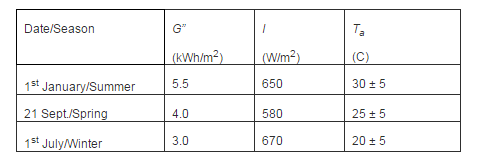
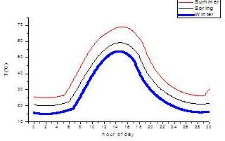
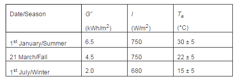
Let us study the performance of a 1.5”-diameter 100-m hose wrapped with a double air-packed transparent polyethylene film mounted over a low-inclined (20°) roof in the Argentinean warm low-latitude location of Salta (25°S). For three different seasonal conditions (see Table 3 [5]) the temperature evolution (without consumption) is illustrated in Figure 3. Here, we can observe this collector can provide hot water along the day all year, but scarcely during night. Three different behaviors are observed along the day:
a)Temperature increases sharply from sunrise to noon and very useful levels are achieved from the early morning.
b)Temperature increases slowly during the afternoon up to reach its peak. After that, it decreases slowly until the sunset.
c)Temperature decreases sharply from sunset till some moment around midnight, in which it matches the surrounding ambient level.
Table 3. Input Parameters for a Warm Low-Latitude Location (Salta, 25°S)
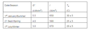
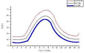
Figure 3. Daily Evolution for Different Seasons on Salta (25°S)
We can understand better these behaviors by considering the evolution of efficiency, illustrated in Figure 4 for the spring case. The collector starts in the morning with an impressive efficiency (80%) and reaches the useful temperature (35C) with a very good (57%) average efficiency. After that, efficiency decreases steadily reaching zero during the afternoon when the peak of temperature occurs. Next, their negative efficiencies explain the cooling effect, which stronger overnight is.
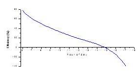
Figure 4. Evolution of Efficiency for the Spring Case
According to this first analysis this collector presents two serious drawbacks:
1) It reaches very quickly the useful temperature but after that its performance is very poor. The maximum resource at noon is much underutilized and it is completely wasted during the evenings. Although this last trend is expected also in low-cost flat collectors, the negative efficiencies observed here is a particular behavior of this kind of collectors.
2) Since the nocturnal cooling is quickly, the excellent peak reached during the day cannot be used during the night. Furthermore, the collector cannot store energy for next day and then it suffers fully the variability of solar resource.
Maybe due to these characteristics this kind of collectors (largely proposed by solar enthusiasts) has not been considered seriously up today except for poor homes in tropical countries. However, we will study its optimizing by using this thermal-hydraulic model as a rational base for considering different climatic conditions.
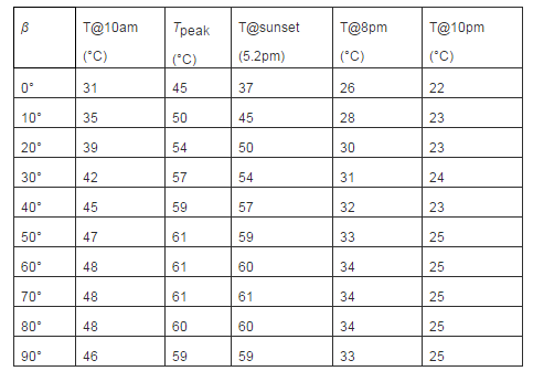
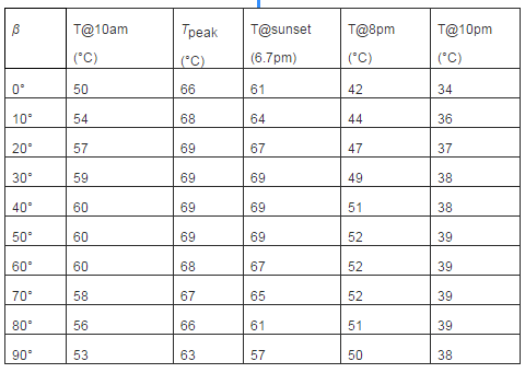
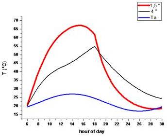
Let us to analyze the effect of roof angle, described by Table 4 for winter case. According to the local latitude the highest peak is obtained around 50°, but steeper roofs can take advantage of last sun rays in the evenings and so, they extend the useful period. A similar behavior is observed in Table 5 for the summer case; although low inclination roofs work better than during winter, the nocturnal performance of steep roofs is still better. This trend can be better understood by comparing the evolution of temperature for 90° and 0° shown in Figure 5. The vertical system shows a second peak during the evenings that explains its improved nocturnal performance. This particular trend show us that the thermal behavior of a hose collector is different than a flat collector; meanwhile a flat collector integrates the energy gained along the diurnal cycle, a hose collector can gain or lost energy during the day and its nocturnal performance is related to the temperature reaches at sunset.
Table 4. Sensitivity Analysis of Roof Inclination in winter on Salta
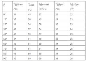
Table 5. Sensitivity Analysis of Roof Inclination in summer on Salta

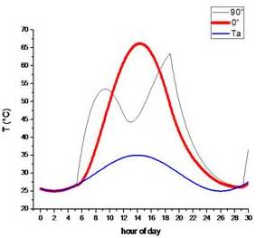
Figure 5. Evolution for Î’= 90° and 0° Roofs in summer in Salta
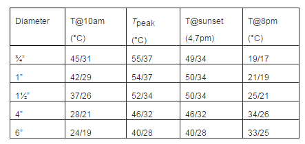
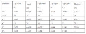
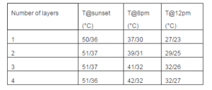
Despite these modest improvements the temperature decreases to ambient level during the night in all cases; it is necessary to get higher thermal inertia in order to provide storage capacity and we expect to get this one by considering larger hose diameters, shown in Table 6. Here very interesting effects can be observed:
1) Thicker tubes get noticeably slower cooling during nights according to their smaller cooling area and higher thermal inertia.
2) Thicker tubes have lower temperatures along the day and then, according to the efficiency function they work on higher average efficiencies1. Hence, we conclude that thicker tubes collects better the solar resource during the whole day.
Although these trends suggest the use of the thickest tube available, on the other hand a thicker tube has a smaller collecting area and therefore it could never reach usable temperatures. Herein, this model can help us to select the optimum design and to better understand how these both (diurnal and nocturnal) opposite behaviors work together. Table 6 presents the sensitivity analysis of diameter for vertical tubes. Here we observe that the thickest tube provides daily storage capacity; the periodical stationary curve (*) for the 6” tube shows a slight improvement in summer but negligible in winter. So, this effect is not practically achieved and then the use of the thickest tube is not recommended.
On the other hand the 1.5” and 4” vertical tubes work well even in cloudy days (c) having a half of G”, but it could be unpractical to put a long 1.5” hose on north walls of a house. Actually only low roof inclinations (around 20°) are used in tropical locations and so this condition is studied with thin hoses for cloudy days. Considering this last case, the vertical 4” tube obtains similar heating than 1.5” hoses during this most-exigent condition. Hence, we can conclude that the optimal choice could be a few 4” vertical tubes mounted on north-face walls or above horizontal roofs. There is standard cheap 4.5” (110mm) tubes made of high-density polyethylene costing 1.5U$D/m, and also PVC tubes costing 3U$D/m; so, a collector made by three 4-m 4.5” tubes provides 115 liters and costs 20 or 40 dollars, respectively. Hence, this simple and practical system could be a good low-cost choice for tropical locations. However, this design needs to be improved for colder locations as we shall see in next section.
Table 6. Results for Vertical (20° for the Second Case) Tubes for Winter/Summer Cases or Cloudy winter (C) Case
Performance on Temperate-Climate Medium-Latitude Locations
We will study now the performance of vertical thick tubes and 1.5” inclined hoses wrapped with double air-packed film layers for Buenos Aires (38°S), a maritime-climate medium-latitude location whose parameters are shown in Table 7 [5]. The sensitivity analysis of the roof angle is presented in Table 8 and Figure 6 for a 1.5” hose in the winter case. Here is observed that low inclinations cause poor performances, similarly but stronger than on low-latitude locations. The collector should not be placed here on roofs having β<30° and the vertical choice is close to optimum. Fortunately (mainly due to architectural reasons) step roofs about 40° are commonly used in this location, and then these two cases (β = 40° and 90°) will be considered.
Table 7. Input Parameters for Buenos Aires (38°S)
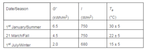
Table 8. Sensitivity of Î’ for 1.5” Hoses on Buenos Aires during winter
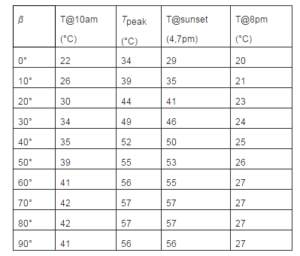

Figure 6. Evolution of 1.5” Hoses on 90° and 0° Roofs in winter at Buenos Aires
Table 9 presents the sensitivity analysis of diameter considering 40° inclined thin hoses and vertical thick tubes for spring case. Here we observe that all systems work well during the day but only thick tubes provide usable water during the night. These behaviors can be better understood by Figure 7. Here, we can observe that the thin hose is heated very quickly but it cannot store the high solar flux received after the noon, which is reflected by its poor overall efficiency1. On the other hand the 4” vertical tube is heated continuously till sunset, reaching good overall efficiencies due to their lower differences (Tm-Ta) involved and also, due to its vertical position that collects the last sun rays. Hence, the 4” vertical tube is our best choice for improving the fall performance. Although the 6” tube has better efficiencies and nocturnal performance, this diameter seems to be too large regarding its smaller area. So, during most part of the year a simple 4” tube collector can provide hot water during the whole day and the desired part of the night. However, this good performance cannot be extended to the winter too. This most-exigent case requires the use of a new design combining the good diurnal heating of the thin hose and the better nocturnal cooling of the thick tube.
Table 9. Results for Fall Case in Buenos Aires; Î’=40° or 90°

Figure 7. Evolution for Vertical 4” and 40° Inclined 1.5” Hoses for Spring Case in Buenos Aires
As was observed, the cooling of a thicker hose during the night is slower due to its larger thermal inertia. Let us quantify this trend by considering the energy equation (1) during the night:
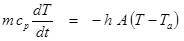 (1)
(1)
Where the water mass, m, and the cooling area, A, can both be related to the hose diameter, D. From here, we can obtain the ratio of cooling for two tubes with the same temperature drop and insulation quality (h), as:
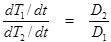 (2)
(2)
Hence, a 1.5” hose is cooled almost three times larger than a 4” tube.
The Mixing-Tube Collector
The analysis of diameter is presented in Table 10 for hoses (β=40°) and vertical tubes in winter for average and cloudy (G”/2) conditions. Here we can see that hoses up to 1” provide usable water even during cloudy days. On the other hand the 4” tube can extend the usable period during the night but it barely provides hot water during cloudy days. Considering both trends, we propose now a mixing system assembled by two parallel lines: a long 1” hose mounted onto the inclined 40° roof and a thick short vertical tube. The long thin hose is used to provide the diurnal demand meanwhile the thick tube is used for satisfying the nocturnal demand. This way, both behaviors can be enhanced related to the single 1.5” hose as Figure 7 illustrates. This more complex design can be solved just by adding a bimetallic thermostat on each exit; this way only hot water flows from each line in every moment. This feature could be enhanced by using two remote-controlled valves and a microcontroller.
Table 10. Results in winter at Buenos Aires for Average/Cloudy Days; Î’=40° or 90° for Hoses or Tubes, Respectively
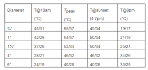
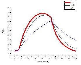
Figure 8. Performance of 40°-Inclined Hoses and 4” Vertical Tube for Winter Case
This mixing system takes advantage of both kind of lines but its nocturnal performance is relatively poor. We can improve the nocturnal cooling of any hose by adding more insulation layer, but in this way their optical efficiency (a0) and heat-losses parameter (a1) are both reduced. In addition, these opposite effects are strong coupled with the daily evolution of the collector temperature and solar flux. This issue will be studied in next section, regarding both (diurnal and nocturnal) behaviors.
The Optimized Mixing System
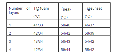
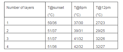
The 1” hose on a 40° inclined roof is optimized in Table 11 for winter average and cloudy (G”/2) conditions regarding the number of insulative layers. Here we can see that a three glazing is the best choice, providing hot water along the whole day even in cloudy days. Furthermore, this trend is valid also regarding 4” vertical tubes considered for improving the nocturnal performance in Table 12. This way, the combined system can provide hot water up to midnight in winter average days.
Table 11. Performance of a 40°Inclined 1” Hose for winter Average/Cloudy Cases
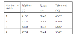
Table 12. Performance of Vertical 4” Tube for winter Average/Cloudy Cases
Performance on a Cold-Climate Location
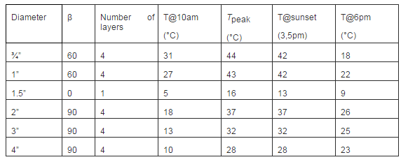
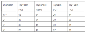
Table 13 presents the climatic parameter of Bariloche (-42°S) an Argentinean sky village close Los Andes Mountain that usually uses step (60°) roofs. Optimizing all parameters for the winter case, we can reach good diurnal performances by using a ¾” four-layer-insulated hose mounted on 60° roofs. This system is compared in Table 14 with a 1.5” single-layer-insulated hose mounted onto a horizontal roof, showing noticeable improvements. Regarding snow concerns, the use of vertical walls could be recommended here. The 3” tube can provides 100 liters by using 23m one meanwhile the 2” tube needs 53 meters for providing the same volume. So, concerns about space limitations could encourage us to select thicker tubes; their performance in winter is not completely good but still they can work as useful preheaters.
On the other hand, the performance during the fall of thick four-layer insulated tubes (see Table 16) is remarkable good, providing usable water more than 4 hours after sunset. Hence, a mixing system can be performed by using a 2” and 4” vertical tubes together with a ¾” hose mounted onto the inclined roof.
Table 13. Parameters for the Cold-Climate Location of Bariloche (42°S)
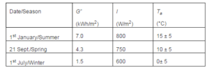
Table 14. Results for Different System during for winter Case
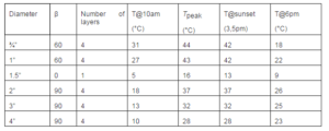
Table 15. Results for Vertical (* 60°) 4-Layer-Insulated Tubes for Spring Case
Conclusions
This paper presents the optimization of a novel low-cost solar collector. It was developed intending to fit the lack of a cheap home-made and self-installation device, which are key to get success in developing countries. Although some home-based solar collectors are been proposed by solar enthusiasts in the past, the thermal-hydraulic analysis and the mixing configuration proposed here have demonstrated that noticeable improvements can be reached. This way, using this theoretical tool it is easy to “tune up” the collector for any particular case, regarding both climatic and architectural conditions. Thus, different diameters, tilt angle and glazing qualities can be used in order to obtain the best solution in any case.
This model has proven to be a useful tool to understand some special characteristics of the hose collector. Meanwhile a standard collector is optimized by its daily performance the hose collector can be designed to optimize its diurnal or nocturnal performances, which are almost independent behaviors. Besides, we realize that the water-pond design improves the performance of thicker tubes having higher efficiencies along the day than thinner tubes. On the other hand, the use of vertical thick tubes has demonstrated to be a very good choice for improving the system performance on medium latitudes.
Although it is necessary to perform much more field tests in order to get accuracy predictions, the high simplicity and flexibility of this water-pond collector allow the user himself to perform it. For example, just by using some few short tubes (testing different conditions) and a low-cost thermometer, the user could extrapolate directly the performance of a similar large collector.
Acknowledgments
Argentinean Du Pont enterprise is acknowledged for its support by funds given through the National Prize Du Pont to Clean Energies 2009 to this project.
References
[1] Juanicó, L. E. & Di Lalla, N. (2013). “A New Low-Cost Plastic Solar Collector,” ISRN Renewable Energy vol. 2013, Article ID 102947, 10 pages, Hindawi Publishing.
Publisher – Google Scholar
[2] Juanicó, L. (2008). “A New Design of Roof-Integrated Water Solar Collector for Domestic Heating and Cooling,”Solar Energy, Vol. 82 (6), 481-492.
Publisher – Google Scholar
[3] Bozkurt, I. & Karakilcik, M. (2012). “The Daily Performance of a Solar Pond Integrated with Solar Collectors,” Solar Energy, Vol. 86(5), 1611-1620.
Publisher – Google Scholar
[4] Hay, H. R. & Yellott, J. I. (1969). “International Aspects of Air Conditioning with Moveable Insulation,” Solar Energy12 (4) 427—430.
Publisher – Google Scholar
[5] Righini, R., Grossi Gallegosm, H. & Raichijk, C. (2005). “Approach to Drawing New Global Solar Irradiation Contour Maps for Argentina,” Renewable Energy, V. 30, 1241-1255.
Publisher – Google Scholar
[6] Jaisankara, S., Ananthb, J., Thulasic, S., Jayasuthakar, S. & Sheebad, K. (2011). “A Comprehensive Review on Solar Water Heaters,” Renewable and Sustainable Energy Reviews, Vol. 15(6), 3045—3050.
Publisher – Google Scholar