Circulating Current Produced in a System of two Inverters Connected in Parallel Due to a Difference Between the Zero-Vector Parameters

Carlos Alonso Sanz, José Miguel Ruiz González and José Antonio Domínguez Vázquez 

Electronics Technology Department. University of Valladolid. C/Paseo del Cauce, Valladolid. Spain

Academic Editor: Andreas Steimel

Cite this Article as:

Carlos Alonso Sanz, José Miguel Ruiz González and José Antonio Domínguez Vázquez (2013), "Circulating Current Produced in a System of two Inverters Connected in Parallel Due to a Difference Between the Zero-Vector Parameters," International Journal of Renewable Energy and Biofuels, Vol. 2013 (2013), Article ID 651616, DOI: 10.5171/2013.651616

Copyright © 2013. Carlos Alonso Sanz , José Miguel Ruiz González and José Antonio Domínguez Vázquez. Distributed under Creative Commons CC-BY 3.0

Abstract

This paper analyzes the imbalances that produce circulating current in a system of two three-phase VSI with SVPWM modulation that, sharing the same DC link, is connected to a grid without galvanic isolation. This analysis has identified a principal imbalance: the difference between the zero-vector parameters of the two inverters. This imbalance is  specific to the SVPWM modulation. The study proposes the correction of the imbalance by measurement algorithms and Proportional Integral Control (using the Ziegler Nichols method to tune the controller), in order to reduce or eliminate the circulation current and increase system performance. It provides a method that does not use an equivalent circuit or a model, determining the value of the imbalance directly and through a system output signal. It has been used PSIM simulation program (version “9.0.3.400”), and the simulations have been taken into account an “ideal” environment. For all simulated cases, this paper analyzes the principal magnitudes and, to obtain the conclusions, shows power data (input power, output power and system performance), in uncontrolled and controlled operation. The simulations allow verifying the goodness of the proposed methods to detect, quantify, control and correct the imbalance, and to improve the system performance.

Keywords: Circulating Current, Inverter, VSI, Zero-Vector parameter, SVPWM

Index Terms

Inverter, Voltage-Source Inverter (VSI), Space Vector Pulse Width Modulation (SVPWM), Isolated-Gated Bipolar Transistor (IGBT), Circulating Current, Zero-Vector Parameter, Proportional-Integral (PI), Digital Signal Processor (DSP).

Introduction

Numerous research studies have been focused on improving performance in the conversion of energy from renewable sources (Schimpf et al., 2008; Petrone et al., 2012; Lopez-Lapena et al., 2012), allowing the parallel connection of inverters the most efficient generation profile of each inverter throughout the day to be taken advantage of.

When two parallel inverters are attached without galvanic isolation (Tuladhar et al., 1997; Mohamed, 2011; Xiao et al., 2011; Massing et al., 2012), an internal circulation current may appear. This current means a loss in the system performance, the appearance of DC currents in the inverters and, consequently, a malfunction of the entire system. These phenomena appear when there are differences that cause imbalances between the homologous output voltages of the two inverters (Chen et al., 2004; Chen, 2006; Yu et al., 2007; Ye et al., 2007; Zhang et al., 2009; Jiang et al., 2009; Ji et al., 2009; Deshang et al., 2012; Jinwei et al., 2012).

System Modeling

The study has been carried out on a system consisting of two three-phase inverters sharing the same DC input link and connected in parallel to a balanced three-phase grid without galvanic isolation, as shown in Fig. 1. The inverters are VSI, with SVPWM modulation (Tsai et al., 2008; Ji et al., 2009; Mohamed, 2011; Beig, 2012). It is usually possible to connect different power inverters, so each one can operate at its maximum power performance. In our study, both inverters have the same power performance, and the output voltage of the system is regulated to a constant value.

651616-fig-1
 Fig.1: System Formed by two VSI Inverters Under Study with SVPWM Modulation.

Fig. 2 represents the IGBTs (Kaplar et al., 2011) and the corresponding anti-parallel diodes for the phase “a” of the two inverters shown in Fig. 1.

In Table I the characteristic analyzed variables are identified for the circuit of Fig. 1; and in Table II, the values of the magnitudes and the components used in the subsequent experimental analysis are specified.

651616-fig-2
Fig.2: Representation of IGBTs and Anti-Parallel Diodes of the Phase “a”.

651616-tab-1,2
Origin of the Circulating Current

In Fig. 1, one of the paths of phase “a” that connects the output of the inverters with the input DC link is marked. Similarly, it is possible to identify all the paths of the circuit. These paths allow the circulation of internal currents, that flow over the source, which produced power losses in each of the inverters connected in parallel. These currents are defined as “circulating currents” (Chen et al., 2004; Chen, 2006; Yu et al., 2007; Ye et al., 2007; Zhang et al., 2009; Jiang et al., 2009; Ji et al., 2009; Chen, 2012; Jinwei et al., 2012). A difference between the voltages of the homologous outputs is also necessary to produce circulating current inside in the path of the current flow.

In the three-phase system of Fig. 1, the equation defining the circulating current is ICir (1):

 
651616-form-1
There are two ways to eliminate the circulation current. The first is by breaking the return paths, using, for example, transformers (which is not the case of the present study). The second is by eliminating the voltage differences between homologous outputs.

The present paper examines the difference between the zero-vector parameters of the two inverters (Zhang et al., 2009; Jiang et al., 2009; Ji et al., 2009) such as the phenomenon that causes imbalances between homologous outputs of the inverters, which in turn causes the appearance of circulating currents. This phenomenon is specific to the SVPWM modulation.

Effect of the Difference Between the Zero-Vector Parameters

When SVPWM modulation (Van der Broeck et al., 1988) is used for generating control signals in a three-phase inverter, it is a common practice to apply a factor or parameter that distributes the width of the zero vectors. This method, defined as “alternating zero-vectors”, maintains the properties of the modulation and eliminates disturbances in SVPWM sequence generation. The parameter that allows the sequence of zero-vectors to be distributed is defined as “K” (Van der Boreck, 1988; Kazmierkowski et al., 1998; Tsai et al., 2008; Zhang et al., 2009; Jiang et al., 2009; Ji et al., 2009; Hongwu et al., 2012; Beig, 2012; Das et al., 2012).

Fig. 3 shows the diagram of control signals for the upper poles of the phases “a”, “b” and “c” of an inverter with SVPWM modulation when the parameter “K” is applied.

 
651616-fig-3
 
 Fig. 3: Sequence of control signals, for an SVPWM inverter on implementing the action of the parameter “K”.

The values of the parameters “d1”, “d2”, “d0” and “k” shown in Fig.3 are defined in (2), (3), (4) and (5).
 
651616-form-2,3,4,5
Where “K” is the zero-vector parameter (which varies between 0 and 1, and its typical value is 0.5), “n” represents the sector, “θ(t)” the angle that the modulating signal describes, and “M” the modulation index.

The difference between the zero-vector parameters of two inverters connected in parallel without galvanic isolation is often due to the different nominal power of each inverter. Even when the two inverters operate at the same power rating, the overall impossible similarity between the two systems results in differences in effective K values of these inverters. There have been many studies on the effects of the zero-vector parameter on the emergence of imbalances and the appearance of internal circulating current phenomena (Zhang et al., 2009; Jiang et al., 2009; Ji et al., 2009).

For the circuit of Fig. 1, we suppose that the zero-vector parameter K1 for the inverter 1, and the zero-vector parameter K2 for the inverter 2 are applied, where K1 ≠ K2. Fig. 4 shows the activation signals and the difference voltage (Va1-Va2) for K1<K2 (Fig. 4-a) and for K1>K2 (Fig. 4-b). In these figures, we have identified three “conduction zones” (numbered from 0 to 2). Table III identifies the devices that conduct current for K1<K2, with negative or positive direction of the load current, in each of the zones. Table IV identifies the devices that conduct current for K1>K2, also with negative or positive direction of the load current, in each of the zones. For the case K1<K2, and also for the case K1>K2, the difference of voltages (Va1-Va2) is independent of the direction of the current “Ia”, so (Va1-Va2) is a square pulse within the period of the carrier signal, having a width defined in (6):

                       Î”w = |ΔK*Ts*d0|                                                                                                               (6)
     
Where ΔK = (K1-K2). Therefore, the signal (Va1-Va2) is a pulsed signal.

 
651616-fig-4
Fig. 4: Activation signals and (Va1-Va2) with a difference between the zero-vector parameters of the two inverters.

The pulse height value is “Vdc” and the width value is directly proportional to the signal d0 (4), which is not a constant value. However, if the approximation that d0 is constant and equal to its mean value, (d0 ), is performed, we can accept that:
 
651616-form-7
Therefore, the value of ΔK is (8):
 
651616-form-8
With this ΔK definition, and applying the PI control (Kazmierkowski et al., 1998; Chen et al., 2004; Yu et al., 2007; Yang et al., 2011), the value of K2 can be corrected and, consequently, we can eliminate the imbalance which causes the appearance of the circulating current. Fig. 5 shows the analyzed circuit, with the applied PI control and the correction system over K2. 
651616-tab-3,4
651616-fig-5
 Fig. 5: Block diagram and proposed control for the imbalance between the zero-vector parameters.

Simulation Results

We have performed the simulation using the formulation explained before. The models have been implemented in “PSIM” (Professional Version 9.0.3.400). Considerations included are that both inverters work ideally and simultaneously, and there are not tolerances in the passive components. The imbalances have been introduced in the inverter 2 so control signals have been fed into inverter 2. The PI controller tuning has been performed using the Ziegler-Nichols method, verifying the system’s stability with the corresponding Bode analysis. The simulation is performed in the sampling period of 1 μsec, with an analysis time horizon of 0.2 sec.

The results displayed below have been obtained for two different cases: for K1>K2 (Fig. 6) and K1<K2 (Fig. 7). Specifically, for the first case, the simulation was performed with K1=0.5 and K2=0.3. For the second case, the simulation was performed for K1=0.5 and K2=0.8.

Figs. 6-a, 6-b, 7-a, and 7-b show the graphs of “ICir“, “Ia1“, and “Ia2“, when the system works freely. Figs. 6-c, 6-d, 7-c, and 7-d show the same magnitudes when applying the proposed control and correction.

651616-fig-6
 Fig. 6: “ICir”, “Ia1” and “Ia2” for K1=0.5 and K2=0.3, without control (Figs. 6-a and 6-b) and with control (Fig. 6-c and 6-d).
 
651616-fig-7
 
 Fig. 7: “ICir”, “Ia1” and “Ia2” for K1=0.5 and K2=0.8, without control (Figs. 7-a and 7-b) and with control (Fig. 7-c and 7-d).

The method proposed in the present paper obtains the imbalance directly from the system and through the difference of the homologous output voltages of the two inverters, without using an equivalent model.

Table V collects the data input and the output power, and the performance of the system, for the two cases analyzed. It should be noted that the reduction of the circulating current increases the system performance. For the first case, in which the initial difference between the zero-vector parameters was 0.2, a performance improvement of 2,96 % has been obtained. For the second case, in which the difference between the zero-vector parameters was 0.3, a performance improvement of 6,29 % has been obtained. These enhancement values are very significant because any slight variation between the zero vector parameters of both inverters generates not only harmonic components at multiples of the fundamental frequency, but also continuous components in the output currents and in the circulation current, with non-negligible values. The use of control eliminates them and substantially increases the performance.

Table V: Power Values and Performance for the Cases Analyzed in Section V
 
651616-tab-5
Conclusion

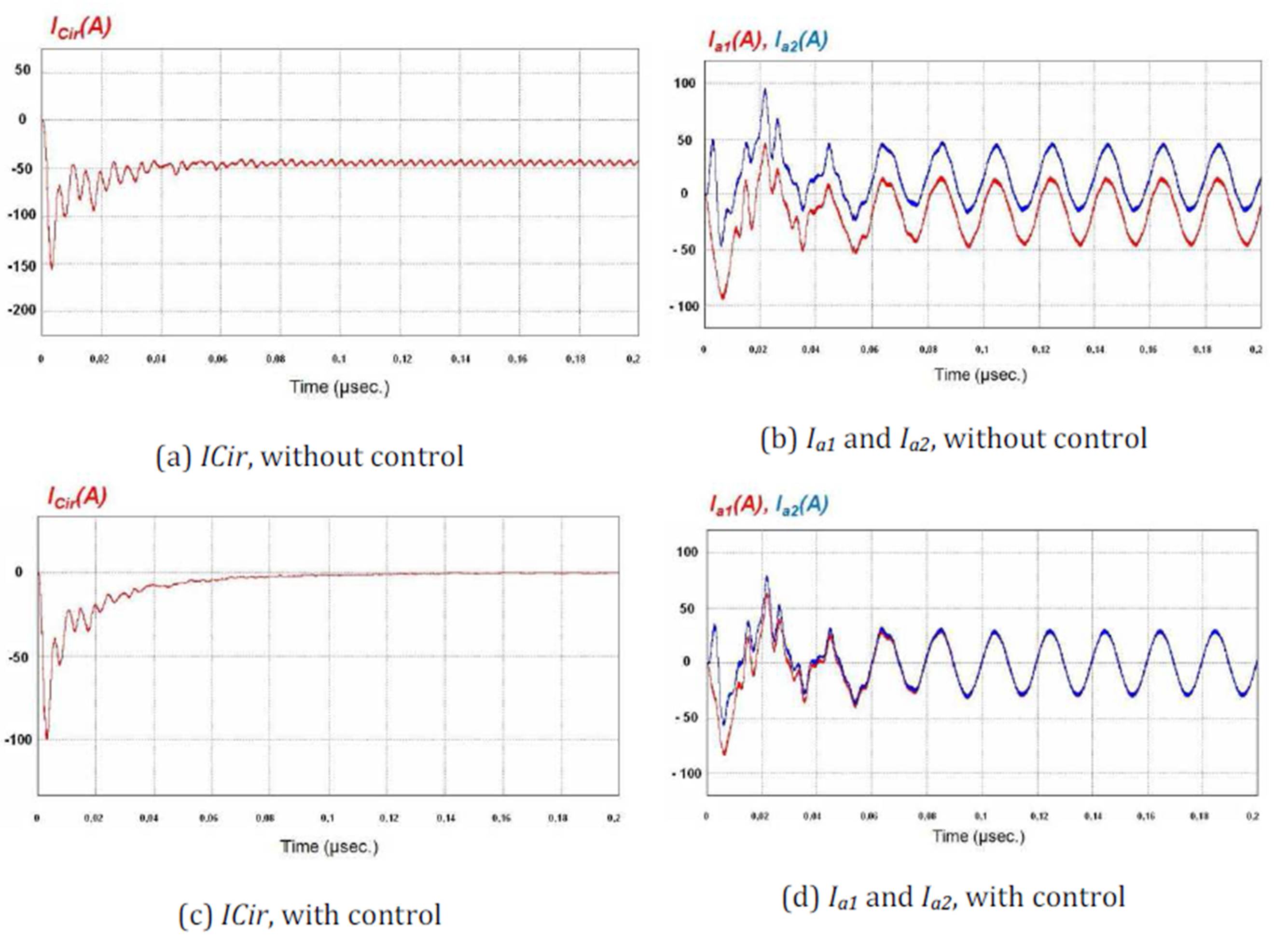
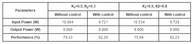
This paper has proposed a method to allow a correction action on one inverter, connected in parallel to another, in order to eliminate the circulation current and thereby increase system performance to the maximum possible value, in case of an imbalance in the zero-vector parameters. The proposed procedure is not excessively complex and does not need a high processing capacity. The proposed method has been validated by quasi-functional simulation, based on a simulator already validated with prototypes of previous inverters.

References

Beig, A.R. (2012) “Synchronized SVPWM algorithm for the overmodulation region of a low switching frequency medium-voltage three-level VSI”, IEEE Transactions on Industrial Electronics, Vol 59 , Issue: 12, pp.: 4545 — 4554.
Publisher 

Chen, L.,  Xiao, L., Gong, C and Yan, Y. (2004) “Circulating current characteristics analysis and the control strategy of parallel system based on double close loop controlled VSI”, IEEE 35th Annual Power Electronics Specialist Conference 2004, Vol 6, pp. 4791-4797.

Chen, T,  (2006)”Circulating zero-sequence current control of parallel three-phase inverters”, Electric Power Applications, IEEE Proceedings, Vol 153, Issue 2, pp 282-288, 2006.

Chen, T.P.  (2012) “Zero-sequence circulating current rduction method for parallel HEPWM inverters between AC bus and DC bus”, IEEE Transactions on Industrial Electronics, Vol. 59 , Issue: 1, pp.: 290 — 300.
Publisher 

Das, S. and Narayanan, G. (2012) “Novel switching sequences for a space-vector-modulated three-level inverter”, IEEE Transactions on Industrial Electronics, Vol. 59 , Issue: 3, pp.: 1477 — 1487.
Publisher 

Deshang, S., Kai, D. , Zhiquinag, G. and Xiaozhong, L. (2012) “Control strategy for input-series—output-parallel high-frequency AC link inverters”, IEEE Transactions on Industrial Electronics, Vol. 59 , Issue: 11, pp.:4101-4111.

Jiang, Z. And Zhang, Y. (2009) “Sliding mode based zero-sequence current mitigation of parallel-connected power converters”, IEEE International Electric Machines and Drives Conference, Pp. 1658-1663.

Ji, S.,  Yong, Y. and Chunqing, Q. (2009) “Control of circulating current for direct parallel grid-connected inverters in photovoltaic power generation”, International Conference on Mechatronics and Automation, pp. 3805-3810.

Jinwei, H., Yun, W.L. and Munir, M.S. (2012) “A flexible harmonic control approach through voltage-controlled DG—grid interfacing converters”, IEEE Transactions on Industrial Electronics, Vol.59 , Issue: 1, pp.: 444 — 455.

Kaplar, R., Brock, R., DasGupta, S., Marinella, M. , Starbuck, A. , Fresquez, A.,  Gonzalez, S. , Granata, J., Quintana, M., Smith, M.  and Atcitty, S.  (2011) “PV inverter performance and reliability: What is the role of the IGBT?”, 37th IEEE Photovoltaic Specialists Conference (PVSC), pp. 1842-1847.

Kazmierkowski, M.P. and Malesani, L. (1998) “Current control techniques for three-phase voltage-source PWM converters: a survey”, IEEE Transaction on Industrial Electronics, Vol. 45, No 5, pp. 691-703.
Publisher Google Scholar

Lopez-Lapena, O., Penella M.T. and Gasulla, M.  (2012) “A closed-loop Maximum power point tracker for subwatt photovoltaic panels”, IEEE Transactions on Industrial Electronics, Vol. 59 , Issue: 3, pp.: 1588 — 1596.
Publisher 

Massing, J.R., Stefanello, M., Grundling, H.A. and Pinheiro, H. (2012) “Adaptive current control for grid-connected converters with LCL filter”, IEEE Transactions on Industrial Electronics, Vol. 59 , Issue: 12, pp.: 4681 – 4693.
Publisher 

Mohamed , Y.A.-R.I. (2011) “Mitigation of dynamic, unbalanced, and harmonic voltage disturbances using grid-connected inverters with  filter”, IEEE Transactions on Industrial Electronics, Vol. 58, Issue: 9, pp.: 3914 — 3924.
Publisher 

Petrone, G., Spagnolo, G. and Vitelli, M. (2012) “An analog technique for distributed MPPT PV applications”, IEEE Transactions on Industrial Electronics, Vol. 59 , Issue: 12, pp.: 4713 — 4722.
Publisher 

Schimpf, F. and Norum  L. E. (2008) “Grid connected converters for photovoltaic, state of the art, ideas for improvement of transformerless inverters”, Nordic workshop on power and industrial electronics, June 9-11.

Tuladhar, A.  Jin, H.  Unger, T. and Mauch, K. (1997) “Parallel operation of single phase inverter modules with no control interconnections”, Twelfth Annual Applied Power Electronics Conference and Exposition, 1997, APEC ’97 Conference Proceedings, Vol 1, pp. 94-100.

Tsai, C., Chang, J. Y., Lai, C.M.,  Juan, Y. L. and Liao, Y. H. (2008), “Modeling of circulating current for grid-connected paralell three-phase inverters”, SICE Annual Conference, Pp. 1319-1322.

Van der Broeck, H. W.; Skudelny, H.- C.; Stanke, G. V. (1988). Analysis and Realisation of a Pulsewidth Modulator Based on Voltage Space Vectors. IEEE Transactions on Industrial Application Vol. 24, No.1, pp. 142-150
Publisher 

Xiao, H.,  Xie, S., Chen, Y. and Huang R.  (2011) “An optimized transformerless photovoltaic grid-connected inverter“, IEEE Transactions on Industrial Electronics, Vol.58 , Issue: 5,  pp.: 1887 — 1895.
Publisher 

Yang, S., Lei, Q., Peng, F.Z. and  Qian, Z. (2011)  “A robust control scheme for grid-connected voltage-source inverters”, IEEE Transactions on Industrial Electronics,Vol. 58 , Issue: 1, pp.: 202 — 212.
Google Scholar

Ye, Z. , Jain, P.K. and Sen, P.C. (2007) “Circulating current minimization in high-frequency AC power distribution architecture with multiple inverter modules operated in parallel”, IEEE Transactions on Industrial Electronics, Vol 54, Nº 5, pp 2673-2687.
Publisher 

Yu, M. , Kang, Y., Zhang, Y., Yin, M., Duan, S., Shan, H. and Chen, G.  (2007) “A novel decoupled current-sharing scheme based on circulating-impedance in parallel multi-inverter system”, 33rd Annual Conference of IEEE Industrial Electronics Society, pp 1668-1672.

Zhang, Y. and Jiang, Z. (2009)“Zero-sequence current dynamics in parallel-connected voltage source converters”, IEEE Electric Ship Technologies Symposium, pp. 189-196.
Publisher 

 
Shares