Introduction
Poor retention related with loss of complete denture bone support is one of the main oral challenges, especially in the elderly edentulous persons. According to Mericske-Stern R (1998), problems regarding integrating dentures are observed with a higher incidence for mandibular dentures than for maxillary dentures. Burns et al. (1995) found that retention is a key element for patient’s satisfaction in removable prosthodontics. Several retention systems (magnets, bars, ball abutments, telescopic crowns, magnets, Locator) have been used to stabilize dentures but none has proved to be ideal. Loosening of overdenture retentive mechanisms were identified by Goodacre et al. (2003) as the most common (33%) prosthodontic complication, requiring routine maintenance to ensure successful long-term outcomes. Fatigue and failure of overdenture attachments negatively affects function, maintenance aspects and patient satisfaction (Mackie et al. 2011)
To overcome the need of multiple maintenance procedures, including replacement of the overdenture components numerical designing with the aid of finite elements – a modern, extremely powerful and efficient method, widely used in the study of stress tension for deformable solid – was proposed to improve overdenture systems’ design.
The principleof the method consists of achieving a geometrical model of the system or the part to be analysed, the discretisation of it in order to obtain a finite elements pattern, defining the properties of the material and the boundary conditions, followed by setting up the problem, solving it and interpreting the results. A special attention must be paid to the numerical pattern, especially to the design of the simplifying hypotheses in order to reduce computing time. An important step is represented by the validation of the calculation model.
Therefore, the aim of this study is to validate the Numerical Simulation Model proposed for Locator (Zest Anchors, Inc.) system by comparing the retention values with the ones mentioned in the Straumann product catalog 2013 in order to optimise the shape of the overdenture systems, to improve the component properties and to study the impact of certain parameters upon the functionality.
Locator was selected for this study due to the fact that it is has been widely used in the past years, is a self-aligning system with dual retention through both external and internal mating surfaces, is resilient, retentive, durable, and have some built-in angulation compensation (Cakarer et al. 2011)
Materials and Methods
In this Finite Element Analysis, Locator system (Zest Anchors, Inc.) is subjected to a shape approximation by a contiguous mesh made of simple polyhedral elements called “finite elements”. Properties are assigned to these elements and they are connected to each other through their vertices, which are called “knots” (Dumont et al 2009). Theoretically, the smaller the finite elements are, the more exact solution given by the Finite Element Method is, but this originates the increase of computer time and cost (Fish and Belytschko 2007). The assigned properties are included in equations of which solutions are the values of the desired variables. The number of unknowns (nodal values) is equal to the number of knots (Fish and Belytschko 2007).
In linear analysis, the displacements are considered small enough so that the hypothesis of reduced deformations may be admitted, and the material is considered having a linear elastic behaviour. It is also admitted that the nature of the boundary conditions remains unchanged during the application of charges.
The Geometric Model
The designed LOCATOR® system for these experimental determinations is the one used with standard Straumann (Institute Straumann AG, Basel, Switzerland) Ø 4.1 RN implant. In order to achieve the geometric 3D model of LOCATOR® system, sketches and data available in Straumann product -catalog (2013) and brochures (2013) have been studied. The components have also been measured with various precision instruments, and all parameters associated with the geometric model were defined in millimeters.
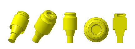
The geometric model of the titanium abutment was accurately reproduced excepting the outer screw to be ignored due to the absence of interest in the problem addressed and with no influence on the obtained results (Fig. 1).

Figure 1: Geometric model of the titanium abutment- LOCATOR® system
The outer screw is designed to perform contact with the corresponding area of the implant. Tightening of the titanium abutment inside the implant was simulated at the corresponding couple (35 N/cm) in accordance to the producer, Institute Straumann AG (Fig. 2).
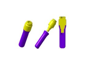
Figure 2: The Ø 4.1 RN implant –titanium abutment group – LOCATOR® system
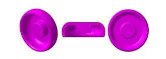
The nylon insert is the system’s component that ensures the retention and the self-alignment. This insert is applied in the titanium housing by means of the special key, and remains pressed inside it. The inner shape of the titanium matrix (housing) allows a rotation of the insert with angles up to ±20°. As a consequence, the size and the profile of the matrix and the nylon insert represent key-factors for the retention force (Fig. 3).

Figure 3: Geometric model of the nylon insert – LOCATOR® system
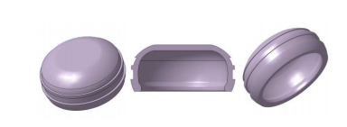
The matrix profile is manufactured in order to retain inside the nylon insert and to allow at the same time its rotation. By adjusting the profiles of these two components, the value of the retention force and of the maximum rotation angle are changing (Fig. 4).

Figure 4: The geometric model of the titanium matrix – LOCATOR® system
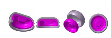
The inner and the outer profile designed represents the best approximation that could be achieved based on the available data and on the measurements made. Where the exact size could not be determined, it has been estimated taking into account the operational mode of the system (Fig.5).

Figure 5: Titanium matrix – Nylon insert
The Finite Elements Design
To perform finite element analysis, Cosmos/M version 2.7 (Structural Research and Analysis Corporation, CA, USA) has been used.
It can be observed in Figure 6 that all the components present rotational symmetry. Due to the fact that displacement is carried out in vertical direction, all along the symmetry axis, the problems to be solved is an axial symmetrical one, and may be discretised using PLANE2D (Nonlinear 2D 4 to 8 knots Isoparametric Plane Stress, Plane Strain and Body of Revolution Element) type elements with 8 knots (Cosmos/M User’s Guide 2001, Bathe et al. 1974).

Figure 6: The LOCATOR® System – functional sub-assemblies
This is an element with two degree of freedom per knot, representing the translations following the axial and radial direction, respectively. The coordinates system of the element is defined by knots 1 and 2 on x axis, y axis is orthogonal on x axis and has the direction given by knot 4. The employment of middle knots ensures a good accuracy of the results, due to the use of second degree interpolation functions.
The reference system axes (Global Cartesian Coordinate System) adopted to define the positions of the knots in the LOCATOR® system’s finite elements model are chosen so that Y axis is the revolution axis (axial symmetry, Fig. 7).
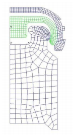
Figure 7: Finite Elements Model of the LOCATOR® system
The components are discretised taking into account the assembling conditions and the system’s operation mode in real environment. For LOCATOR®, the problem becomes more complicated due to the interferences between the components in the static condition.
The Material Model
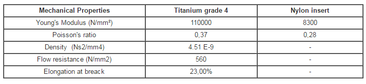
The material used to define the numerical model of the overdenture system is titanium grade 4 for the dental implant, abutment and metallic housing and nylon for the insert. The chemical composition of unalloyed grade 4 Titanium for Straumann Implants and Abutments (conforms to ISO 5832-2 standard) and Straumann Product Catalog 2013 is as follows: O (0,40 max), Fe (0,50 max), C (0,10 max), N (0,05 max), H (0,01 max) and Ti (Balance).
The mechanical properties of these materials used for simulation are presented in table 1.
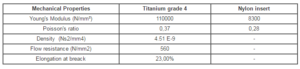
Table 1: Mechanical Properties of unalloyed grade 4 Titanium for Straumann Implants/Abutments and Nylon insert (according to Straumann Product Catalog 2013 and http://www.matweb.com).
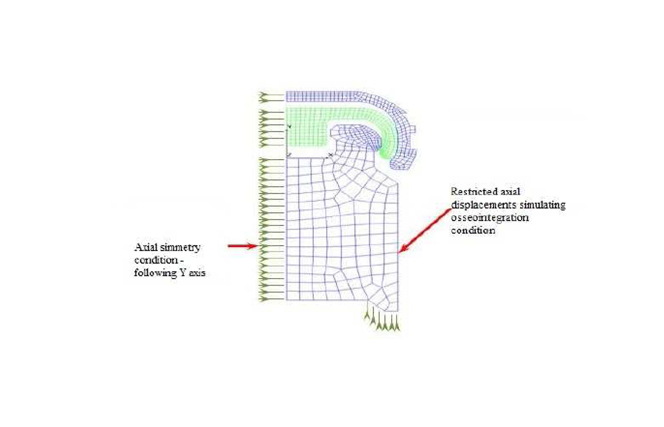
The Boundary Conditions
The boundary conditions imposed to implants displacements simulate the osseointegration conditions (Figure 8).
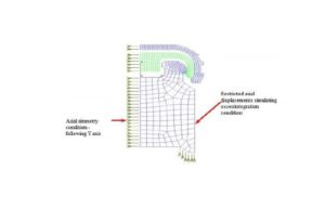
Figure 8: Boundary Conditions in displacements – LOCATOR® displacements
The model represents a complete mandibular edentulous case with atrophic alveolar ridges. In this case, the retention is provided by the implant – connector system only. In this model, the implant and the lower part of the abutment were ignored due to the insignificant deformation during function and the lack of influence for the retention forces.
Due to the fact that the model is performed in x0y plan, the axial symmetry condition is carried out by restricting the displacements of all knots in x direction, regardless of the part they belong to (Figure 8).
The titanium matrix and the nylon insert are able to freely move on y axis direction. In order to numerically determine the retention force, the nylon insert must be displaced on the titanium abutment under the same conditions imposed during the experimental determination, with a rate approximately to 50 mm/min.
The effective displacement of the titanium – nylon insert is less than 1 mm. Consequently, the numerical simulation will be carried out by 1 mm displacement of the titanium matrix on y direction during one second. In order to provide convergence, the time is defined by two intervals, the first part with lower displacement rate due to the interferences existing between the components. From functional considerations, the initial interference shall take place between the titanium matrix and the nylon insert, respectively between the nylon insert and the titanium abutment. Moreover, the nylon insert may rotate inside the titanium matrix, and in this case it may freely glide on y direction.
In order to simulate the contact in this case, the Node-to-Line GAP bi-dimensional element is used (Cosmos/M User’s Guide 2001). This type of element may be defined taking into consideration the friction between bodies (Coulomb friction). Due to initial interferences and to the simultaneous contact between bodies, the solution has not been convergent for the friction case. As a consequence, the simulations will not include frictions between bodies, and will retain only the maximum value of the retention force, not its variation with time.
In order to define the contact between two bodies, a body is declared “contactor”, meanwhile the other is designated as “target”. For LOCATOR® system, two such areas are defined: between the titanium matrix and the nylon insert, and between the nylon insert and the titanium abutment, respectively. In addition, the two areas show interferences in the initial position, (parts from the piece overlaps and will perform the initial tightening). The titanium matrix and the titanium abutment are defined as “target” because they are manufactured from a rigid, less deforming material. The contact area between the “target” is defined by a series of contact lines (in 2D problems).
Figure 9 is a graphic for two target areas. The red color shows the contact area defined for the titanium matrix, and the black color shows the contact line defined for the titanium abutment.
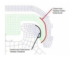
Figure 9: Defining contact areas – LOCATOR® system
Similar, the contact area of the „contactor” body is defined by knots. For each knot a GAP element is assigned. The nylon insert is defined as “contactor” body for both contact groups. The GAP elements are placed in the most likely contact place: on the inner surface of the insertion for the titanium abutment, and on the outer surface of the insertion for the titanium matrix (Figure 10).
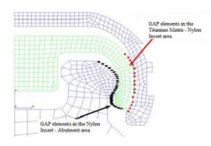
Figure 10: Defining contact elements – LOCATOR® system
Each GAP element may contact any line associated to its group. As seen in Figure 9 and Figure 10, respectively, the contact between these three bodies has been limited to certain areas defined on the “contactor” and on the “target”, respectively. Thus, the time needed to calculate the contact areas is substantially reduced.
In its initial position, the overdenture system provides contact between all the three bodies. The geometry for the initial position is created on purpose with interferences to simulate the mounting conditions. The first interval, 0 to 0.1 seconds, is due to establish the contact areas and to reach the components equilibrium within the overdenture system mounted. The simulation of the assembly consisting of the titanium matrix and the nylon insert displacement will continue for the purpose of determining the retention force.
Numerical Analysis
Besides the material’s non-linearities, the large displacements and deformations, the continuous change of the contact conditions, the simulation of the initial mounting condition also occurs. In order to reach the convergent solution two calculation intervals have been defined, as discussed previously, and reduced the time unit accordingly.
The control of this solution is the force, using the iterative method of Newton-Raphson equations (Bathe 1977 & 1982, Bathe et al 1974, Zienkiewicz 1991). The tangent matrix of rigidity is reformulated at each time unit. The maximum iterations’ number in a time unit is 100, and the equilibrium iterations convergence is 0.1 %.
Results
In order to validate the calculation model, the way the system replied to the requests, the values and the distribution of the displacements and stresses have been verified. The quality and quantity of the results are verified in order to evaluate the structure’s deformations according to the expectations. In this case, the quality of the way the system works may be easily checked by visual means, observing the nylon insert deformations.
From the quantitative point of view, in Figure 11, the radial displacement field – following the X axis direction and respectively axial displacement field – following the Y axis direction, are showed. On the radial direction, a slight deformation of the titanium elements and a significant deformation of the nylon insert are noticed. Following the axial direction, a more accentuated displacement of the nylon insert as well as an imposed displacement of the titanium matrix which apparently has a solid rigid movement due to high rigidity are observed.

Figure 11: Radial and axial displacements field – on X and Y axis directions
The field of radial displacements is displayed on a real shape of the structure (on 1:1 scale). The knots displacements are synchronized for all the components and the maximum value on radial direction is 0.03 mm is reached at the extreme edge of the nylon insert as it was expected.
In the radial section, the nylon insert flexing is practically noticed when the LOCATOR® system is displaced. Consequently, the retention force is given by the inner profile of the system and by the rigidity of the contact parts. All the three bodies entering in contact influence the value of the retention force by their geometric shape and by the rigidity. Figure 12 illustrates the radial stresses field on the deformed shape of the structure at 1:1 scale. A good continuity in the contact areas may be noticed, leading to the conclusion that the system is correctly simulated within the limits of the simplified hypotheses made.
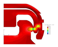
Figure 12: Radial displacements field – on X axis direction (Mpa)
For each time unit, the value of the force needed to displace the LOCATOR® retention system is available. The maximum retention force is 23.93 N (equivalent to 2.44 kilogram force), the value is compliant with the experimental and manufacturer’s data. The 2.44 kg f corresponds, according to Straumann catalog 2013, to the white color nylon insert (normal retention force).
As a result of the simulation, the distribution of the stresses in components is also obtained. In Figure 13, the distribution map of the equivalent Von Mises stresses displayed on the deformed shape of the system is shown. On the same figure, the non-deformed shape (the initial position of the structure – white color with red color knots) is also displayed.

Figure 13: Von Mises equivalent stresses map (MPa) / Iso Line / rear view
It is to be noticed from the stress maps that certain areas of the nylon insert may reach the flow limit (the dark red color areas on the insert). These areas are areas with possible residual deformations. Due to the fact that the exact data about the material are not available, the stress values occurring cannot be calculated. It is to be noticed that the optimization of the system using the finite element can be obtained with this model.
By changing the lamella’s profile, the value of the stresses may be considerably reduced without affecting the performance of the retention system. In this study, the geometry has been approximated and the optimization’s calculation was not considered as aim.
Conclusions
The Finite Element Model designed for Locator system and the assigned properties leading to simulated retention force values close to those given in the Straumann catalog 2013 demonstrate that the numerical simulation properly surprised the physical phenomena. Therefore, the results obtained using this model can be considered relevant.
The finite element model can be used to optimize the shape of the overdenture system, the materials of which its components are made; one can study the impact of certain parameters on the functionality, etc. Furthermore, having the tension values available, one can evaluate fatigue strength of components, and optimizations can be made for longer life span of the retention system.
From the operational point of view, using the finite element model, it can be asserted that the constructive solution of the LOCATOR® offers prerequisites of a reliable product.
Finite Element Method is a technique with strong potential and proven results in many areas of biomedical engineering including dentistry.
Acknowledgment
This study was supported by Camident Ro SRL, Bucharest, Romania
References
1.Bathe, K.J. (1982) Finite Element Procedures in Engineering Analysis, Prentice-Hall, New Jersey, USA
2.Bathe, K.J., Wilson, E.L. and Iding, H.R. (1974) NONSAP – A Structural Analysis Program for Static and Dynamic Response of Nonlinear Systems, Vol. I & II, USA
3.Bathe, K.J. (1977) ADINA – A Finite Element Program for Automatic Dynamic Incremental Nonlinear Analysis of Temperatures, USA
4.Burns, D.R, Unger, J.W, Elswick, R.K. Jr and Giglio, J.A. (1995) “Prospective clinical evaluation of mandibular implant overdentures: Part II—Patient satisfaction and preference”. J Prosthet Dent ; 73: 364-9
Publisher – Google Scholar
5.Cakarer, S, Can, T, Yaltirik, M. and Keskin, C. (2011) “Complications associated with the ball, bar and locator attachments for implant-supported overdentures”. Medicina oral, patologia oral y cirugia bucal 16: e953-959.
Publisher – Google Scholar
6.Cosmos/M A Complete Finite Element Analysis System 2.7 User’s Guide (2001) Structural Research and Analysis Corp. pg. 4-158 to 4-163 and 4-239 [Online], [Retrieved January 20, 2014], http://www.stresscalc.ru/cosmos/UsersGuide.pdf
7. Dumont, E.R, Grosse I.R. and Slater G.J.(2009) “Requirements for comparing the performance of finite element models of biological structures”. Journal of Theoretical Biology, 256(1): p. 96-103.
Publisher – Google Scholar
8. Fish J.B. and Belytschko T.(2007) “A First Course in Finite Elements”. John Wiley & Sons, West Sussex, England
Publisher – Google Scholar
9. Goodacre CJ, Bernal G, Rungcharassaeng K, Kan JY.(2003) “Clinical complications with implants and implant prostheses”. J Prosthet Dent; 90: 121-32.
Publisher – Google Scholar
10.Mackie, A, Lyons, K, Thomson. W.M, Payne, A.G. (2011) “Mandibular two-implant overdentures: prosthodontic maintenance using different loading protocols and attachment systems”. Int J Prosthodont. 24:405–416
Google Scholar
11. Mericske-Stern R. (1998) “Treatment outcomes with implant-supported overdentures: clinical considerations”.
J Prosthet Dent. Jan;79(1):66-73.
Google Scholar
12.Online Materials Informations [Online], [Retrieved January 20, 2014] http://www.matweb.com/
13.Straumann “Product Catalog 2013” [Online], [Retrieved December 15, 2013],
http://www.straumann.us/content/dam/internet/straumann_us/resources/brochurecatalogue/product-catalogs/en/2013.
Product.Catalog.pdf
14.Straumann “Restoring Straumann implants with Locator Abutments” [Online], [Retrieved December 15, 2013],
http://www.straumann.com/content/dam/internet/straumann_ca/resources/brochurecatalogue/brochures/en/CALIT
118%20Locator%20Brochure.pdf
15.Zienkiewicz, O.C. and Taylor, R.L. (1991) The Finite Element Method, Fourth Edition, McGraw-Hill Book Company, Vol.2