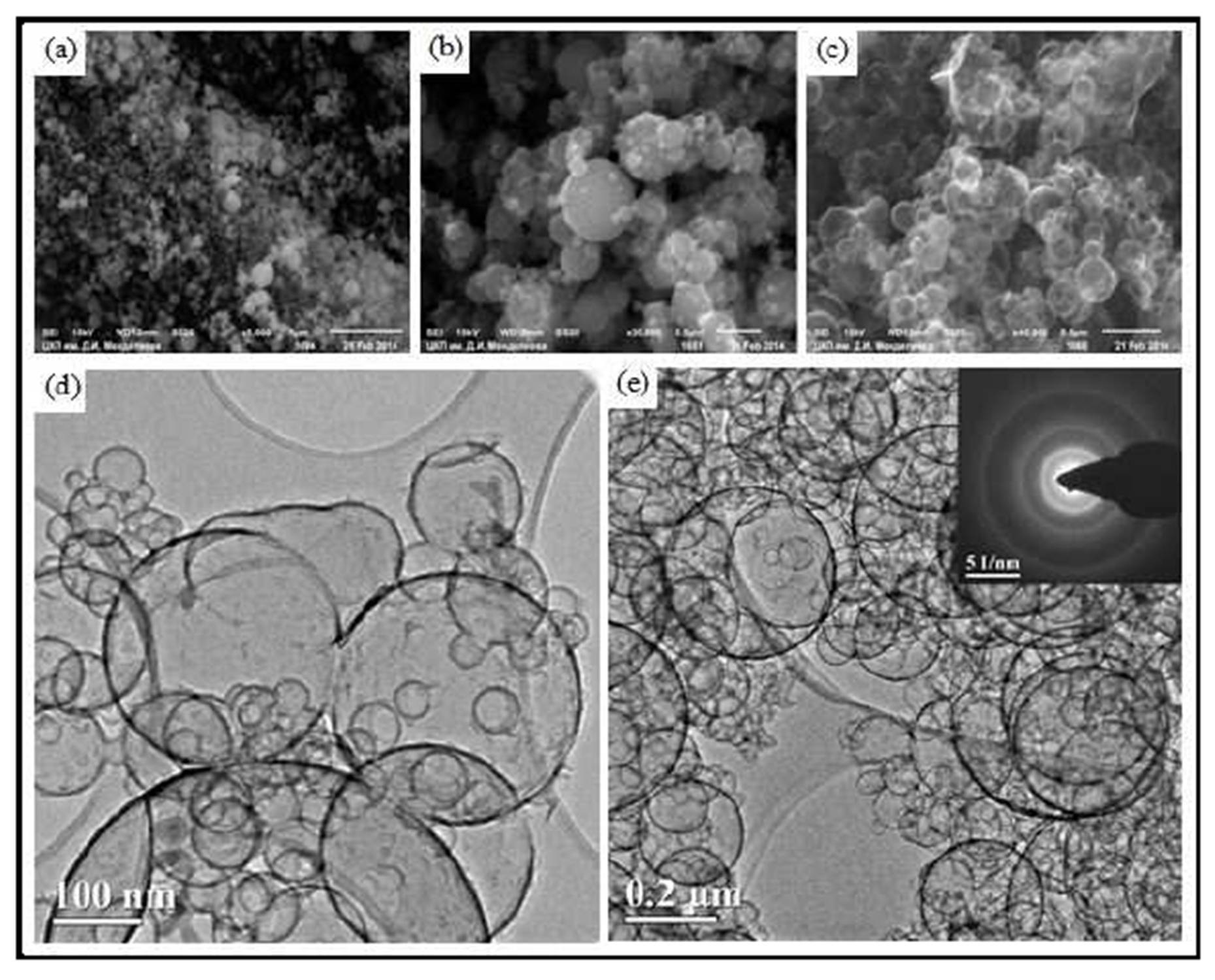
The carbon spherical shells with the thickness of some nanometers become not strong and do not keep their habitus. Therefore destroyed spheres are seen on some of the pictures (Fig 6 d), but its number is negligible. Coalescent particles are also observed.
In 1959 Cullis et al (1959) has showed that carbon deposited from methane on silica substrate had a normal graphite structure, in other words represented graphene (which was not yet discovered).
The electron diffraction pattern (Fig 6 e) corresponds to the polycrystalline graphite structure of carbon deposit.
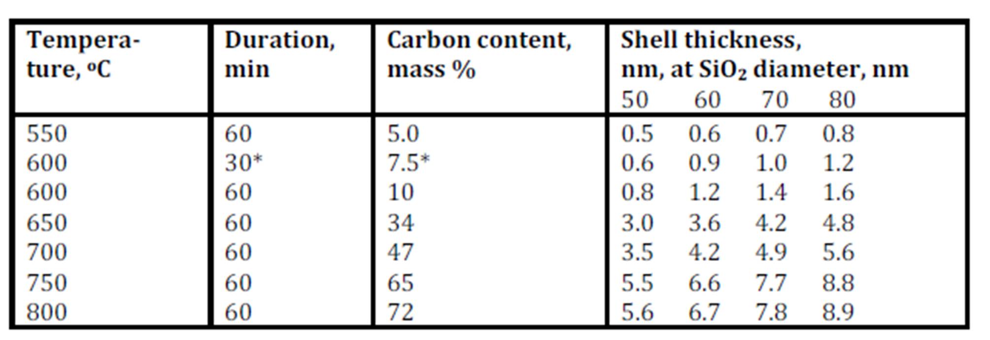
The lower is the pyrolysis temperature, the higher are porosity and specific surface values of shells. The specific surface of shells synthesized at 600 oC was 175 m2/g, whereas specific surface value of a matrix SiO2 particles was equal to 12—13 m2/g.
Carbon shells having thickness lower than 5—7 nm in the case of individual particles must be transparent or semitransparent, as it was shown earlier by Kaplas and Svirko (2012). Our shells are transparent in electron beam, however as a whole they retain black color.
The unique spherical carbon shells synthesized here have high electrical conductivity and can be used as electrode material for capacitive deionization (electrosorption) of waste water effluents.
Conclusion
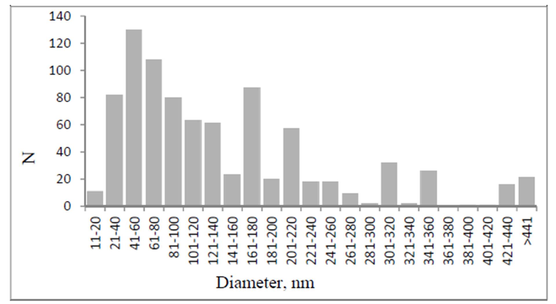
A simple method for the preparation of 3D architectures is developed via a pyrolytic process. The methane pyrolysis at temperatures of 500—900 оС on the spherical nanoparticles of SiO2 allows to get a Ñоre-shell hybrid composites, and the consequent dissolution of SiO2 matrix leads to formation of isolated hollow carbon shells. The main part of these shells have diameters of 40 — 80 nm with a shell thickness of 1—12 nm. The values of shell density and specific surface are temperature dependent: The lowering of synthesis temperature leads to the reduction of density and to the increasing of specific surface.
Acknowledgement
The authors thank Dr. E. Melnichenko for the granting of SiO2 samples; V. Zhigalina for TEM investigation; Mendeleev Research Center for SEM investigation; O. Vinokurova for the measurement of specific surface.
Conflict of interests
The authors have declared that no conflict of interest exists.
References
1. Bachmatiuk, A., Mendes, R. G., Hirsch, C., Jähne, C., Lohe, M. R., Grothe, J., Kaskel, S, Fu, L., Klingerer, R., Eckert, J., Wick, P., and Rümmeli, M. H. (2013) ‘Few-Layer Graphene Shells and Nonmagnetic Encapsulates: A Versatile and Nontoxic Carbon Nanomaterial,’ ACS Nano, 7 (12) 10552—10562.
Publisher – Google Scholar
2. Böttger-Hiller, F., Kempe, P., Cox, G., Panchenko, A., Janssen, N., Petzold, A., Thurn-Albrecht, T., Borchardt, L., Rose, M., Kaskel, S., Georgi, C., Lang, H., and Spange, S. (2013), ‘Twin Polymerization at Spherical Hard Templates: An Approach to Size-Ajustable Carbon Hollow Spheres with Micro- and Mesoporous Shells,’ Angewandte Chemie International Edition, 52 (23) 6088—6091.
Publisher – Google Scholar
3. Brüggert, M., Hu, Z., and Hüttinger, K. J. (1999) ‘Chemistry and kinetics of chemical vapor deposition of pyrocarbon. VI. Influence of temperature using methane as a carbon source,’ Carbon, 37 (12), 2021—2030.
Publisher – Google Scholar
4. Chen, D., Ji, G., Ma, Y., Lee J. Y., and Lu J. (2012 a) ‘Graphene-Encapsulated Hollow Fe3O4 Nanoparticle Aggregates as a High-Performance Anode Material for Lithium-Ion Batteries,’ Applied Materials & Interfaces, 3 (8), 3078—3083 .
5. Chen, X., Kierzek, K., Cendrowski, K., Pelech, I., Zhao, X., Feng, J., Kalenczuk, R. J., Tang, T., and Mijowska, E. (2012 b) ‘CVD generated mesoporous hollow carbon spheres as supercapacitors,’ Colloids and Surfaces A: Physicochemical and Engineering Aspects, 396, 246—250.
Publisher – Google Scholar
6. Cullis C.F., Manton J.E., Thomas G.B., and Wilman H. (1959) ‘The Structure and Crystal Growth of Carbon Deposits Formed by Pyrolysis of Some Hydrocarbons and Chlorohydrocarbons,’ Acta Crystallographica, 12 (5), 382—384.
Publisher – Google Scholar
7. Davydov, S. Yu., Kryukov, A. Yu., Gerya V. O., Izvol’skii I. M., and Rakov, E. G. (2012) ‘Preparation of a Platelike Carbon Nanomaterials Using MgO as a Template,’ Russian Journal of Physical Chemistry, 48 (3) 244—248.
Google Scholar
8. Hayashi, T., Hirono, S., Tomita, M., and Unemura, S. (1996) ‘Magnetic thin films of cobalt nanocrystals encapsulated in graphite-like carbon,’ Nature, 381 (6585) 772—774.
Publisher – Google Scholar
9. He, G., Evers, S., Liang, X., Cuisiner, M., Garsuch, A., and Nazar, L. F. (2014) ‘Tailoring Porosity in Carbon Nanospheres for Lithium-Sulfur Battery Cathodes,’ ACS Nano, 7 (12), 10920—10930.
10. Hussain S.T., Iqbal M. (2011) ‘Pyrolysis of methane by catalytic properties exhibited by ceramics,’ Journal of Analytical and Applied Pyrorysis, 90 (2) 106—111.
Publisher – Google Scholar
11. Inagaki, M., Miura, H., and Konno, H. (1998) ‘A new simple process for carbon coating of ceramic particles using poly(vinyl chloride),’ Journal of European Ceramic Society, 18 (8) 1011—1015.
Publisher – Google Scholar
12. Inagaki, M., Kobayashi, S., Kojin, F., Tanaka, N., Morishita, T., and Tryba, B. (2004) ‘Pore structure of carbon coated on ceramic particles,’ Carbon, 42 (15) 3153—3158.
Publisher – Google Scholar
13. Inagaki, M., Morishita, T., Toyoda, M., Tsumura, T., and Konno, H. (2006) ‘Carbon Coatings of Ceramics,’ Tanso, 2006 (224) 308—317.
14. Ismach, A., Druzgalski, C., Penwell, S., Schwartzberg, A., Zheng, M., Javey, A., Bokor, J., and Zhang, Y. (2010)‘Direct chemical vapor deposition of graphene on dielectric surfaces,’ Nano Letters, 10 (5) 1542—1548.
Publisher – Google Scholar
15. Jayaprakash, N., Shen, J., Moganty, S. S., Corona, A., and Archer, L. A. (2011) ‘Porous Hollow Carbon@Sulfur Composites for Higy-Power Lithium-Sulfur Batteries,’ Angewandte Chemie International Edition, 50 (26), 5904—5908.
Publisher – Google Scholar
16. Jerng, S. K., Yu, D. S., Kim, Y. C., Ryou, J., Hong, S., Kim, C., Yoon, S., Efetov, D. K., Kim, P., and Chun, S. H. (2011, a) ‘Nanocrystalline graphite grown on sapphire by carbon molecular beam epitaxy,’ Journal of Physical Chemistry C, 115 (11) 4491—4494.
Publisher – Google Scholar
17. Jerng, S. K., Yu, D. S., Lee, J. H., Kim, C., Yoon, S., and Chun, S.-H. (2011, b) ‘Graphitic carbon growth on crystalline and amorphous oxide substrates using molecular beam epitaxy,’ Nanoscale Research Letters, 6 (1) 565—574.
Publisher – Google Scholar
18. Kaplas, T. and Svirko, Yu. (2012) ‘Direct deposition of semitransparent conducting pyrolytic carbon films,’ Journal of Nanophotonics, 6 (1) 061703.
Publisher – Google Scholar
19. Kim, M., Yoon, S. B., Sohn, K., Kim, J. Y., Shin, C.-H., Hyeon, T., and Yu, J.-S. (2003) ‘Synthesis and characterization of spherical carbon and polymer capsules with hollow macroporous core and mesoporous shell structures,’ Microporous and Mesoporous Materials, 63 (1—3) 1—9.
Publisher – Google Scholar
20. Kim, J. H., Fang, B., Yoon, S. B., and Yu, J.-S. (2009) ‘Hollow core/mesoporous shell carbon capsule as an unique cathode catalyst support in direct methanol fuel cell,’ Applied Catalysis B: Environmental, 88 (3—4) 368—375.
Publisher – Google Scholar
21. Li, L., Seng, K., Chen, Z., Liu, H., Nevirkovets, I. P., and Guo, Z. (2013) ‘Synthesis of Mn3O4-encapsulated graphene sheet nanocomposites via a facile, fast microwave hydrothermal method and their supercapacitive behavior,’Electrochimica Acta, 87 801—808.
Publisher – Google Scholar
22. Liu, J., Zhu, Y., Liang, J., and Qian, Y. (2012) ‘Synthesis of In3O3/Carbon Core-Shell Nanospheres and their Electrochemical Performance,’ International Journal of Electrochemical Science, 7 (2012) 5574—5580.
23. Qiao, Z. A., Guo, B., Binder, A. J., Chen, J., Veith, G. M., and Dai S. (2013) ‘Controlled synthesis of mesoporous carbon nanostructures via a “silica-assisted” strategy,’ Nano Letters, 13 (1) 207—212.
24. Rümmeli, M. H., Kramberger, C., Grüneis, A., Ayala, P., Gemming, T., Büchner, B., and Pichler, T. (2007)
‘On the Graphitization Nature of Oxides for the Formation of Carbon Nanostructures,’ Chemistry of Materials , 19 (17) 4105—4107.
Publisher – Google Scholar
25. Rümmeli, M. H., Schäffel, F., de los Arcos, T., Haberer, D., Bachmatiuk, A., Kramberger, C., Ayala, P., Borowiak-Palen, E., Adebimpe, D., Gemming, T., Leonhardt, A., Rellinghaus, B., Schulz, L., Pichler, T., and Büchner, B. (2008) ‘On the graphitization role of oxide support in carbon nanotube CVD synthesis,’ Physica Status Solidi B, 245 (10) 1939—1942.
Publisher – Google Scholar
26. Rümmeli, M. H., Bachmatiuk, A., Scott, A., Börrnert, F., Warner, J. H., Hoffmann, V., Lin, J. H., Cuniberti, G., and Büchner B. (2010 a) ‘Direct Low-Temperature Nano-Graphene Synthesis over a Dielectric Insulator,’ ACS Nano, 4 (7) 4206—4210.
Publisher – Google Scholar
27. Rümmeli, M. H., Shäffel, F., Bachmatiuk, A., Adebimpe, D., Trotter, G., Börrnert, F., Scott, A., Coric, E., Sparing, M., Rellinghaus, B., McCormic, P. G., Cuniberti, G., Knupfer, M., Schultz, L., and Büchner, B. (2010 b) ‘Investigating the Outskirts of Fe and Co Catalyst Particles in Alumina-Supported Catalytic CVD Carbon Nanotube Growth,’ ACS Nano, 4 (2) 1146—1152.
Publisher – Google Scholar
28. Scott, A., Dianat, A., Börrnert, F., Bachmatiuk, A., Zhang, S., Warner, J. H., Borowiak-Paleń, E., Knupfer, M., Büchner B., Cuniberti, G., and Rümmeli, M. H. (2011) ‘The catalytic potential of high-k dielectrics for graphene formation,’ Applied Physics Letters, 98 (7) 073110.
Publisher – Google Scholar
29. Shin, E. S., Kim, M. S., Cho, W. I., and Oh, S. H. (2013) ‘Sulfur/graphitic hollow carbon sphere nanocomposite as a cathode material for high-power lithium-sulfur battery,’ Nanoscale Research Letters, 8 (1) 343—354.
Publisher – Google Scholar
30. Su, F., Zhao, X. S., Wang, Y., Wang, L., and Lee J. Y. (2006) ‘Hollow carbon spheres with a controllable shell structure,’ Journal of Materials Chemistry, 16 (45) 4413-4419.
Publisher – Google Scholar
31. Teunissen, W., de Groot, F. M. F., Geus, J., Stephan, O., Tence, M., and Colliex, C., (2001)
‘The Structure of Carbon Encapsulated NiFe Nanoparticles,’ Journal of Catalysis, 204 (1) 169—174.
Publisher – Google Scholar
32. Wang, S., Huang, X., He, Y., Huang, H., Wu, Y., Hou, L., Liu, X., Yang, T., Zou, J., and Huang, B. (2012)‘Synthesis, growth mechanism and thermal stability of copper nanoparticles encapsulated by multi-layer graphene,’Carbon, 50 (6) 2119—2125.
Publisher – Google Scholar
33. Wang, D., Tian, H., Yang, Y., Xie, D., Ren, T.-L., and Zhang, Y. (2013) ‘Scalable and Direct Growth of Graphene Micro Ribbons on Dielectric Substrates,’ Scientific Reports, 3, 1348. DOI: 10.1038/srep01348.
Publisher – Google Scholar
34. Wen, Y., Zhu, Y., Langrock, A., Manivannan, A., Ehrman, S. H., and Wang, C. (2013)
‘Graphene-Bonded and Encapsulated Si Nanoparticles for Lithium Ion Battery Anodes,’ Small, 9 (16) 2810—2816.
Publisher – Google Scholar
35. Xuan, S., Hao, L., Jiang, W., Gong, X., Hu, Y., and Chen, C. (2007)
‘A facile method to fabricate carbon-encapsulated Fe3O4 core/shell composites,’ Nanotechnology, 18 (3) 035602.
Publisher – Google Scholar
36. Yan, Z., Peng, Z., Sun, Z., Yao, J., Zhu, Y., Liu, Z., Ajayan, P. M., and Tour, J. M. (2011)
‘Growth of bilayer graphene on insulating substrates,’ ACS Nano, 5 (10) 8187—8192.
Publisher – Google Scholar
37. Yang, S., Feng, X., Ivanovichi, S., and Müllen, K. (2010) ‘Fabrication of Graphene-Encapsulated Oxide Nanoparticles: Towards High-Performance Anode Materials for Lithium Storage,’ Angewandte Chemie International Edition, 49 (45), 8408—8411.
Publisher – Google Scholar
38. Yoon, S. B., Sohn, K., Kim J. Y., Shin, C.-H., Yu, J.-S., and Hyeon, T. (2002) ‘Fabrication of Carbon Capsules with Hollow Macroporous Core/Mesoporous Shell Structures,’ Advanced Materials, 14 (1) 19—21.
Publisher – Google Scholar
39. Zhu, S., Zhang, D., Chen, Z., and Zhang, Y. (2009) ‘Controlled synthesis of core/shell magnetic iron oxide/carbon systems via a self-templated method,’ Journal of Materials Chemistry, 19 (41) 7710—7715.
Publisher – Google Scholar