1,2,5AGH University of Science and Technology, Kraków
3,4PONAR Wadowice, Łaziska Górne, Poland
Volume 2024,
Article ID 484764,
Communications of the IBIMA,
11 pages,
DOI: doi.org/10.5171/2024.484764
Received date: 1 September 2023; Accepted date: 23 January 2024; Published date: 23 February 2024
Academic Editor: Gabriela Bucur
Cite this Article as:
Bartłomiej BONAR, Tomasz BURATOWSKI, Piotr ROSIKOWSKI, Paweł PAC And Mariusz GIERGIEL (2024)," Magnetic Safety Equipment Development for Ship Cleaning Robot", Communications of the IBIMA, Vol. 2024 (2024), Article ID 484764, https://doi.org/10.5171/2024.484764
This paper presents a comprehensive development process of magnetic adhesion modules designed for mobile robots working in shipyards, performing hull-cleaning duties. The main aim is to prepare a secure system that will allow robots to safely navigate on ferromagnetic hulls. Typical process involves sandblasting performed by human personnel, which creates highly dangerous working conditions and requires numerous safety precautions to prevent both human accidents and environmental contamination related to cleaning medium spreading. Delegating this task to robot allows the deployment of specially designed cleaning equipment, reducing accidents’ chance, medium spreading and its usage thanks to dedicated salvage system. Existing literature lacks precise information on magnetic force calculations due to the high complexity of the problem that can be accounted to magnet shape or used materials. This study could be used as a guideline for development of similar equipment. The Finite Element Method Magnetics (FEMM) software is utilized for modelling and simulating numerous solutions that align with the working conditions of the robot. To generate a high-density, low-range magnetic field, which would be highly compatible for working conditions, Halbach array was used and comparison with single magnet of equivalent size was provided. The paper also discusses material choice and geometric considerations for the chassis. Experimental measurements of physical system involved multiple magnets’ configurations. This study provides a thorough comparison of numerical predictions and an actual performance of developed magnetic adhesion modules, establishing a field-tested design that can serve as a valuable reference for future work.
Keywords: mobile robot, Halbach array, magnetic adhesion
Introduction
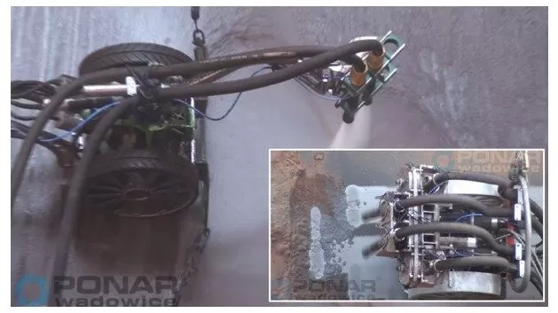
The traditional method of cleaning hulls in shipyard industry is based on sand blasting, which has to be performed in specific conditions to reduce environmental pollution. Those include spreading curtains over ship and performing activities only in windless weather, increasing costs and workload. Another problem is safety of workers, as apart from respiratory dangers of manual sandblasting, working at heights poses its own problems. To solve this problem, authors prepared innovative remotely controlled mobile robot equipped with dedicated cleaning tool (fig. 1). Robot, aside from performing cleaning duties in a much safer way, can also be equipped with medium-salvage system, that greatly reduces pollution and further decreases the need for additional covers. The medium itself can also be reused, what further decreases operating cost. Such system is feasible only by utilizing robot, as it easily fulfills requirement of keeping nozzles near surface, what could be problematic through manual means.
Fig 1. PONAR cleaning robot at work
One of the critical systems were magnetic adhesion modules that would allow robot to safely navigate on vertical hulls. First, considerations for using permanent magnets and Halbach array are presented. Then, FEMM software is used for magnets’ size and arrangement selection. Next, requirements for casing are presented with description of used materials and roles of most important parts. Lastly, testing station is presented, along with experimental data and their analysis.
Magnets Arrangement
As the critical safety system, magnetic adhesion modules had to be immune to power shortage. Because of considerable weight, batteries could be used, as such, the only source of power was using a cable. Because of possible cutoff, magnetic modules could not work actively for the same reasons why manipulators use passive brakes. For those reasons, the possibility of using electromagnets has been excluded. As permanent magnets were chosen, the remaining issue was maximizing force to mass ratio given geometric boundaries. For the sake of comparison with previously prepared modules, N38 magnets were used. It also provided an additional safety buffer in case of developed module showing subpar performance when constructed and tested, as stronger magnets of the same size could be freely used.
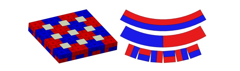
To maximize the usage of magnets’ energy, Halbach array has been implemented. It is a special arrangement of permanent magnets that generates a unique magnetic field with distinct properties. It is named after Klaus Halbach, the physicist who first proposed and analyzed this magnetic configuration in his study (1980). The primary characteristic of a Halbach array is its ability to produce a strong magnetic field on one side while nearly canceling out the magnetic field on the opposite side. The conventional arrangement of permanent magnets typically results in a magnetic field that is relatively uniform on both sides of the array. However, in a Halbach array, the magnets are specifically oriented to create a spatially varying magnetic field (fig. 2). Originally, synchrotrons development was used as described in another Halbach’s research (1985), but later it found use in magnetic bearings in a study by N. Wang et al (2016) or magnetic trains levitation system described in a paper by W. Tang et al (2021).
Development began with simulation comparison of different magnets’ arrangements. Numerical verification was prepared using FEMM environment. It is a specialized simulation software for solving problems from fields of magnetics, electrostatics, heat flow or current flow. FEMM is most frequently used for solving magnetics’ problems. It was used in the development of military HMMWV’s generator described in a paper by A. Al-Adsani and N. Schofield (2009) or magnetic launch system for carriers developed by D. I. D. staff (2022). Additionally, the software has a simple interface, which makes it user friendly. Simulations were prepared for 2 methods of magnetization of single body magnets, used for comparison, and for Halbach array using 30mm cube magnets (fig. 2). Force generated by magnetic field on a ferromagnetic object can be described as:
Where χ is magnetic susceptibility per unit volume, µ is relative magnetic permeability of given environment, dV denotes unit volume and Hz is magnetic field strength as described in H. Li et al (2022). In the described case, Hz is a variable related directly to distance between magnets and ferromagnetic hull. It is difficult to find strict equation that could describe field strength in function of distance as it may differ depending on shape of magnet and attracted body. In general, experiments describe this relation as function of distance cubed as stated by Mike W. and Tom on the University of Illinois site (2007). According to it, simplified equation of force can be stated as:
Where ψ contains all physical constants described in previous equation and d is gap between magnets and ferromagnetic body. Although not precise, this description shows the importance of keeping distance to the absolute minimum, while creating attraction force big enough to ensure safety in case of momentary increase in distance.
Fig 2. Schematics of magnets used in work: 2D Halbach array (left), radial polarization, horizontal polarization, single row Halbach array (right)
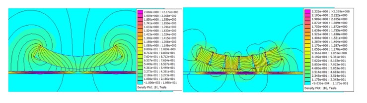
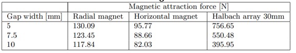
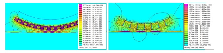
The usage of Halbach array resulted in forces several times bigger than when using single body magnets (fig. 3, tab. 1). Field with smaller range but higher intensity provided attraction forces several times bigger than their counterparts from solid magnets.
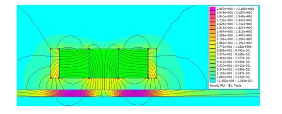
Fig 3. Flux density charts for: solid magnet with radial magnetization (left), 30x30x30mm Halbach array (right)
Table 1: Values of simulated forces for settings with variable gap and 6mm ferromagnetic sheet for different magnets
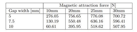
Geometric constraints of robot chassis allowed only for a small amount of 30x30x30mm magnets to be placed, which resulted in a highly heterogenous field. It posed a question if an arrangement of more but smaller magnets with a more uniform magnetic field, but of shorter range, would result in greater overall attraction force. The idea was tested with a series of smaller commercially-available magnets’ sizes (fig. 4, tab. 2).
Fig 4. Flux density charts for different sizes of Halbach array: 10x10x10mm (left), 25x25x25mm (right)
Table 2: Values of simulated forces for settings with variable gap and 6mm ferromagnetic sheet for different Halbach array sizes
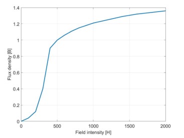
Results of simulations pointed out 25x25x25mm magnets as the best solution in terms of generated attraction force. Further analysis shows a threshold slightly under 800N that was approached by most of settings, but crossed by none. This occurrence is possibly caused by magnetic saturation (fig. 5). This phenomenon is related to the mechanism of magnetizing materials, where magnetic dipoles of material are being reoriented. When most of them are already reoriented under external magnetic field, further increase in external field intensity provides only marginal increase in magnetization strength, resulting in saturation described in a study by E. Purcell and D. Morin (2013). Below is shown B/H curve based on measurements presented in Electricala2z forum.
Figure 5: Magnetization curve of iron
Case Design for Magnets Array
The primary objective of the adhesion module’s case was to address the challenge of enduring repulsion forces resulting from magnetic interactions between the embedded magnets, while ensuring their stable orientation and secure attachment to the robot’s frame. Notably, the lower part of the case, situated on the side with a reinforced magnetic field, experienced the most substantial forces during operation. Additionally, this section played a crucial role in maintaining the desired gap width between the magnets and the ferromagnetic hull, thus achieving a minimal thickness of this part was crucial. For this part, a titanium alloy sheet with cut out openings was used. Pure titanium is proved to be diamagnetic, while alloys can be paramagnetic or ferromagnetic. If ferromagnetic material was placed in front of magnetic field (in this case between magnets and hull), the field would significantly weaken, what would be highly unfavorable. Because of those reasons, highly paramagnetic alloy was used. As per FEMM simulation, the use of such material resulted in almost no decrease in attraction forces (fig. 6). Additionally, several openings have been cut out to maximize field penetration and to make placing magnets inside easier.
Figure 6: Simulation with titanium sheet and aluminum case
The sides of the case, which held the titanium sheet using a form, fit experienced notable strain as well. Also, to reduce costs, making them using titanium alloy was not feasible. Initial choice was to use stainless steel, which has good strength and resistance to corrosion big enough to survive in maritime environment. However, this solution posed a question of what negative influence it would have on magnetic field, as stainless steel is a ferromagnetic material. Different mediums and materials have varying magnetic permeability, which describes the ability to support the formation of magnetic fields in a material. Relative permeability is stated as:
Where is magnetic permeability in the void. The higher the value, the easier it is to magnetize the material, what in the given case would result in a bigger amount of magnet’s energy being spent on chassis instead of hull. Typically used ferritic stainless steel has relative permeability of around 1000 – 1800 as stated on Engineering ToolBox site (2016). To reduce further increase in costs by using material with lesser permeability, a design that would minimize steel volume inside the main magnetic flux was needed.
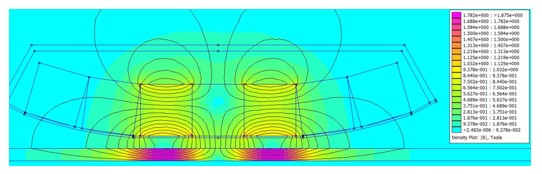
Using material strain MES simulation, it had been verified that small handles will be able to keep titanium sheet in place under the highest theoretical attraction forces. Next, FEMM simulation was again used to check the influence of ferromagnetic on the side of the magnetic field (fig. 7). The result showed that using magnetic alloy might decrease attraction force by even 25% of original value. The chosen solution was to use alloy with low magnetic capabilities that was available at hand.
Figure 7: Simulation with stainless steel walls
The remaining parts, placed on top of the module and responsible for module assembly and installation, were made from aluminum, as those weren’t under any considerable strains.
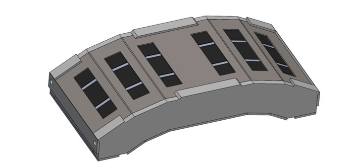
Figure 8: Case prototype
Experimental Verification using Prototype
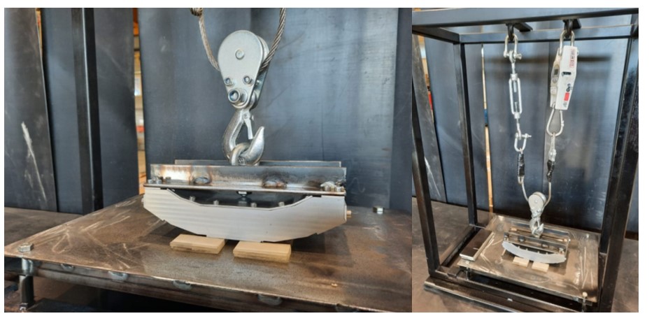
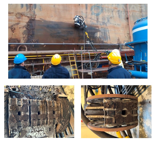
The testing site employed a movable pulley mounted on the module, which was connected to a dynamometer on one side and a roman screw on the other, allowing for the adjustment of the gap’s width (see fig. 9). The steel sheet was utilized to simulate the ship’s hull, and the minimal gap width was determined using a series of wooden and plexiglass distance plates. However, it is important to note that the methods employed in the experiment introduced some visible impacts on the results in the form of hysteresis.
Figure 9: Testing station
During the testing, a significant challenge was encountered when attempting to find the “equilibrium” position of the module between floating and resting on the plates before taking readings. To minimize the aforementioned error, all measurements were conducted multiple times, with each repetition initiated away from the plates to avoid bias.
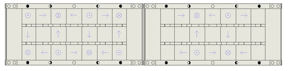
Additionally, the experiment explored the impact of different settings on the achieved force. Specifically, external rows of magnets were removed in a separate configuration to assess their 7 influences on the actual attraction forces (see fig. 10).
Figure 10: Schematics of magnets settings: full (left), shortened (right)
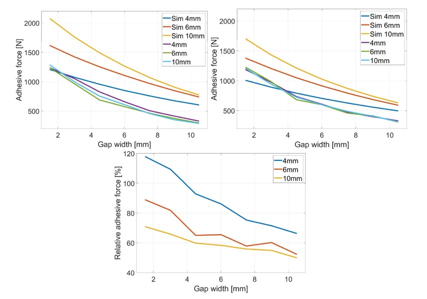
Figure 11: Attraction force curves for different settings: full setting, shortened setting, relative values
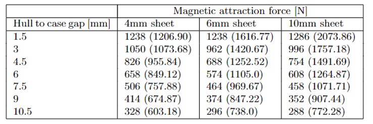
Table 3: Averaged measurements (and simulations) for full setting with variable gap and different thickness of ferromagnetic material
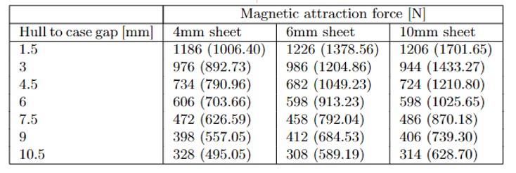
Table 4: Averaged measurements (and simulations) for full setting with variable gap and different thickness of ferromagnetic material
Measurements’ analysis shows that despite simulation results, external rows of magnets have residual influence on attraction forces (tab. 3, 4). It also shows that simulation accuracy decreases with gap width, being around only 50% on extreme case (fig. 11). It clearly points out the order of magnitude of security factor that has to be included when relying on simulation results in the development of such systems.
Discussion
In this study, the primary focus was on achieving the desired adhesive force for the magnetic adhesion module. During the magnet selection process, careful consideration was given to the characteristics of the technological manufacturing process, which not only impacts the cost but also the feasibility of production. Consequently, cube magnets, available in various sizes from commercial providers, were chosen as the preferred option. While the generated force was a significant aspect, an equally critical concern was the containment of magnets within the casing. Although creating dedicated magnets with mounting holes might seem like a simpler solution, the associated cost and potential reduction in the lifespan of naturally brittle magnets must be taken into account.
The presented solution offers complete scalability, as depicted in figure 10. By adjusting the angles and size of the casing, different cube sizes can be accommodated, enabling customization for various hulls and operating conditions. The utilization of a Halbach array enables the maximization of magnet energy on the working side, while concurrently limiting the field density on the robot’s side, a highly advantageous feature for protecting internal electronics.
The experimentation data revealed that the required penetration depth of the magnetic field for optimal energy utilization is relatively shallow compared to the overall construction size. As such, the high-density, low-range field configuration demonstrates substantial potential for a wide range of working conditions.
The main limitation of the presented solution lies in the simulation aspect of the project. While FEMM, a widely utilized software, was employed for various projects in the world and multiple undertakings by the authors, demonstrating the reliability of the calculations, there is considerable disparity observed between simulation data and experimental results, particularly in cases with larger gap sizes. This discrepancy is believed to come from the sensitivity of magnetic systems to varying working conditions, which are difficult to fully capture and describe using equations. To partially validate these findings, conducting similar simulations using alternative software should be considered in future research.
In conclusion, this study successfully addresses the critical challenge of achieving the desired adhesive force for the magnetic adhesion module. The presented scalable solution, employing a Halbach array configuration, demonstrates promising results for a wide range of working conditions. Nonetheless, further investigations and validation through alternative simulation approaches are recommended to enhance the overall understanding and accuracy of the magnetic system’s performance.
Modules described in this work served as reference for further development regarding case construction and new models are used on real-life robot (fig. 12).
Figure 12: Adhesion modules on robot: robot working on ship, modules next to main wheels, module on secondary wheel
Acknowledgment
Authors would like to sincerely thank AGH UST and the Department of Robotics and Mechatronics for financing the submission.
The development process was conducted as a cooperation between PONAR Wadowice and RIOT Technologies under INNOSHIP POIR.01.02.00-00-0105/19 project and resulted in patent application number 2019.08.12 P430859.
References
Al-Adsani, A., S. and Schofield, N. (2009), ’Hybrid permanent magnet generators for electric vehicle applications,’ Proceedings of IEEE International Electric Machines and Drives Conference, DOI: 10.1109/IEMDC.2009.5075440, 3-6 May 2009, Miami, USA, 1754-1761
I. D. staff, (2023), ”Electro-magnetic launch recovery for carriers,’ Defense Industry Daily, [Online], [Retrieved 22.09.2023], https://www.defenseindustrydaily.com/emals-electro-magnetic-launch-for-carriers-05220/
Halbach K. (1980), ‘Design of permanent multipole magnets with oriented rare earth cobalt material, ’Nuclear Instruments and Methods, 169 (1), 1-10
Halbach K. (1985), ‘Application of permanent magnets in accelerators and electron storage rings,’ Journal of Applied Physics, 57(8), 3605-3608
Li, H., Wu, B., Tang, R., Wang, Y., Liu, X. and He, C. (2022), ’Nondestructive evaluation of carburized layer depth in furnace tubes of cr35ni45nbma using magnetic field distortion and magnetic attraction force measurement methods,’ Measurements, [Online], [Retrieved 22.09.2023], https://www.sciencedirect.com/science/article/pii/S0263224122001385
Purcell, E. and Morin, D. (2013), ’Electricity and Magnetism 3rd Edition, Cambridge University Press, New York
The Engineering ToolBox (2016), ’Permeability, [Online], [Retrieved 22.09.2023], https://www.engineeringtoolbox.com/permeability-d_1923.html
, Mike and Tom (2007), ’How does distance affect the strength of a magnet, [Online], [Retrieved 22.09.2023], https://van.physics.illinois.edu/ask/listing/419
Wang, N., Wang, D., Chen, K. and Wu, H. (2016), ’Research on analytical model and design formulas of permanent magnetic bearings based on halbach array with arbitrary segmented magnetized angle, ’Journal of Magnetism and Magnetic Materials, 410, 257-264
Wang, T., Xiao, L., Xia, W., Yang W. and Wang, Z. (2021),’2-d and 3-d analytical calculation of the magnetic field and levitation force between two halbach permanent magnet arrays,’ IEEE Transanction on Magnetics, 57(4), 1-8